Table 7-1 Sensor Connections
Sensor Phase Wire Color Terminal Pin Assignment
Current L1/A Red 13 + (S1)
Current L1/A Black 14 Neutral (S2)
Current L2/B Red 15 + (S1)
Current L2/B Black 16 Neutral (S2)
Current L3/C Red 17 + (S1)
Current L3/C Black 18 Neutral (S2)
Voltage L1/A Brown 19 +
Voltage L1/A Black 20 Neutral
Voltage L2/B Brown 21 +
Voltage L2/B Black 22 Neutral
Voltage L3/C Brown 23 +
Voltage L3/C Black 24 Neutral
NOTE
The wire colors shown are valid for standard sensors only. Follow the instructions of the sensors you use.
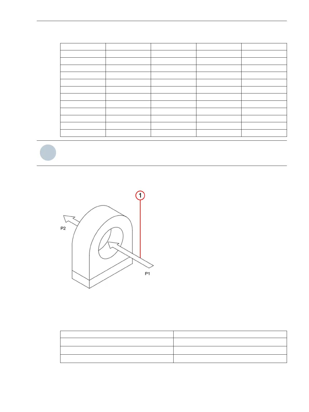
Power-Flow Direction
The following figure shows the power-flow direction from P1 to P2.
[le_sfcm_powflodir-160624, 1, --_--]
Figure 7-10 Power-Flow Direction from P1 to P2
(1) Power-Flow Direction from P1 to P2
Table 7-2 Power-Flow Direction Parameters for Solidly-Grounded Systems
Phase Parameter Value
I
1
power-flow direction Not reversed
I
2
/I
N
power-flow direction Not reversed
I
3
power-flow direction Not reversed
Table 7-3 describes the power-flow direction parameters for the isolated/compensated-grounded systems.
Connection Diagrams
7.3 Sensor Connections
SICAM, Feeder Condition Monitor, Manual 75
E50417-H8940-C580-A4, Edition 03.2019