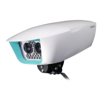
Product Features Description
Sicore II Installation and Commissioning Guide
667/HB/52600/000 Issue 2 Unrestricted
4. Product Features Description
4.1. Serial Input / Output
The Sicore II camera is fitted with multiple isolated I/O ports that allow the unit to interface
with many type of external equipment such as:
• Serial trigger devices
• External modem
• Instation
4.1.1. Ethernet
This interface provides an auto detecting 10/100/1000 Ethernet interface and will generally
be used for fixed infrastructure instation communications. To achieve a Gigabit connection
the cable must be restricted to a maximum length of 100m.
4.1.2. RS232
This interface provides an isolated RS232 port with RTS & CTS flow control lines.
4.1.3. RS422/RS485
This interface provides an isolated 4 wire RS422 or 2 wire RS485 port. The port mode is set by
camera configuration.
4.2. Digital Input / Output
The Sicore II camera is fitted with multiple isolated I/O ports that allow the unit to interface
with many type of external equipment such as:
• External visible or IR flash lighting units
• Lane or carriageway vehicle detectors for external triggering
• Barrier control
The voltage between any of the isolated interface pins and system ground
must NOT exceed 50V DC
Apart from the four digital inputs which have their own isolated ground
return, all other isolated interfaces share the same isolated ground
4.2.1. Digital Inputs
Four isolated digital inputs are provided. These four inputs share one common isolated
ground return. This isolated ground is NOT connected to any other of the cameras ground
points. These inputs have the following specification:
• 12-24V DC input
• Input current limited to 7mA
• ELV level isolation
• Programmable polarity

 Loading...