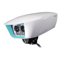
System Components
Sicore II Installation and Commissioning Guide
667/HB/52600/000 Issue 2 Unrestricted
5.6.3. Aux 1 Connector
This 19 way connector carries the following signals:
• Isolated Digital I/O
The connector has the following pinout:
No. Pin Function Colour Core
1 J Isolated Digital Input 1 + Brown 1
2 S Isolated Digital Input 2 + Red 1
3 G Isolated Digital Input 3 + Orange 1
4 T Isolated Digital Input 4 + Yellow 1
5 H Isolated Ground for Digital Inputs Only * Black 1
6 R
1
Isolated Sicore.in.2 bit 1 + - -
7 L Isolated sicore.out.1 bit 1 / Digital Output 1 + Brown 2
8 N Isolated sicore.out.1 bit 2 / Digital Output 2 + White 2
9 K Isolated sicore.out 1 bit 3 / Digital Output 3 + Grey 2
10 U Isolated sicore.out.1 bit 4 / Digital Output 4 + Pink 2
11 P Isolated Ground for Digital Outputs Yellow + Green 2+2
12 D Isolated Relay Output Normally Open Blue 1
13 C Isolated Relay Output Common White 1
14 B Isolated Relay Output Normally Closed Green 1
15 M
1
Isolated Power Switch Power Input - -
16 F
1
Isolated Power Switch Power Output - -
17 E
1
Isolated Power Switch Ground - -
18 V Isolated Sicore.in.2 bit 2 Signal Input Red 3
19 A Isolated Sicore.in.2 bit 2 Ground Return Black 3
Table 10 – Aux 1 Connector Pinout
Note: (*) The isolated digital inputs do not share the common isolated ground used on all of
the other isolated interfaces. The dedicated isolated ground return for the inputs is on Pin
Ref. H
1
– Functions not available with standard cables as listed in
. If these functions are needed a custom cable will be required.

 Loading...