System Components
Sicore II Installation and Commissioning Guide
667/HB/52600/000 Issue 2 Unrestricted
5.6.1. Cable Connections
All three cables (Main, Aux1, Aux2) use the same cable form. This cable is described in Table
8.
No. Colour Core Set Description
1 Red 1 Cat5e Data Cable
2 Orange 1 Cat5e Data Cable
3 Blue 1 Cat5e Data Cable
4 White 1 Cat5e Data Cable
5 Brown 1 Cat5e Data Cable
6 Yellow 1 Cat5e Data Cable
7 Green 1 Cat5e Data Cable
8 Black 1 Cat5e Data Cable
9 Brown 2 3 pairs
10 White 2 3 pairs
11 Grey 2 3 pairs
12 Pink 2 3 pairs
13 Yellow 2 3 pairs
14 Green 2 3 pairs
15 Red 3 1.5mm
2
16 Black 3 1.5mm
2
Table 8 – Cable Cores
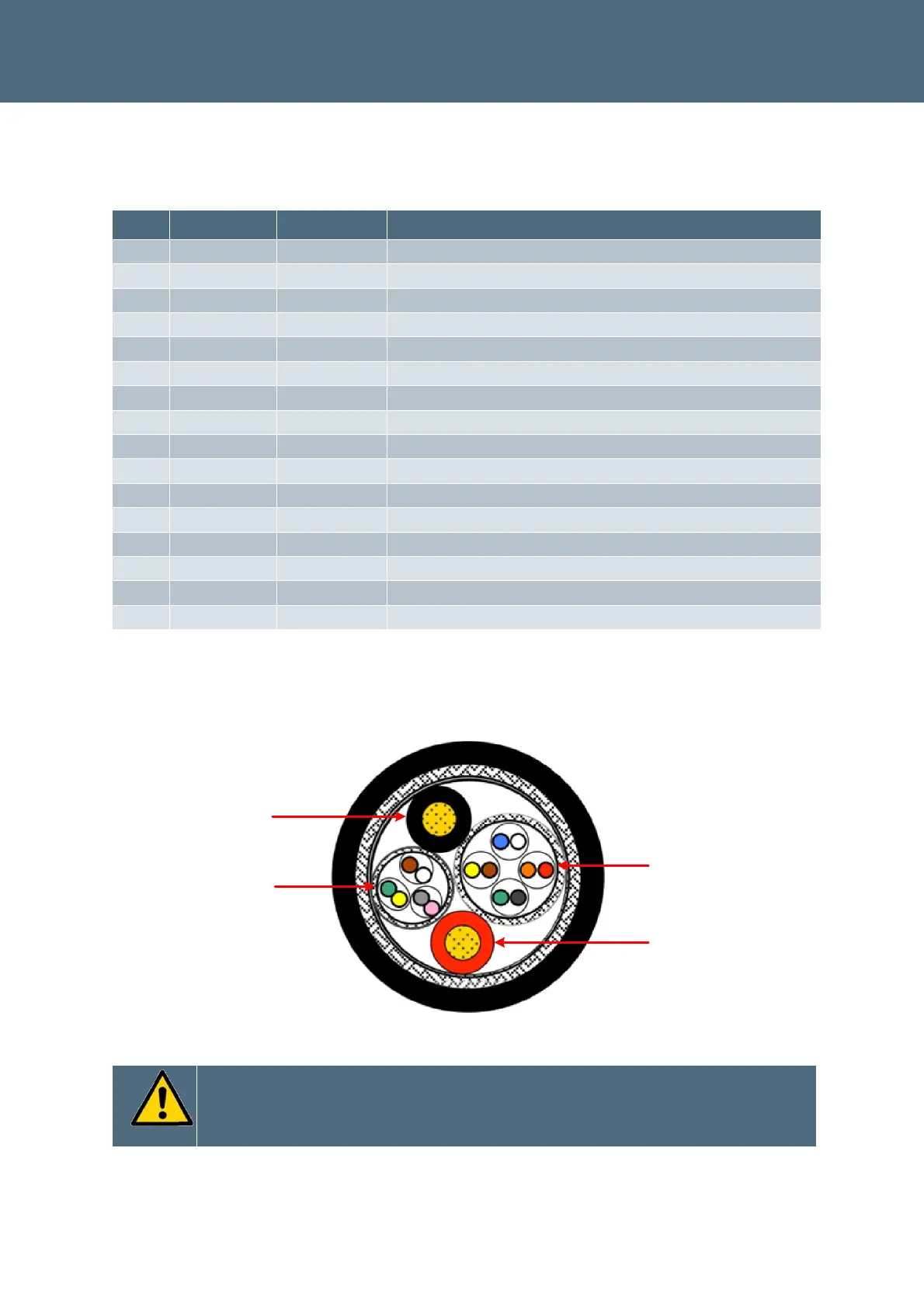
The cable makeup core sets are shown in Figure 7.
Core set 1 – Ethernet style
Core set 3 – 1.5mm
2
Power
Core set 3 – 1.5mm
2
Power
Core set 2 – 3 Pairs
Figure 7 – Cable Makeup
Ensure the Main Cable screen is terminated to the enclosure Ground – This
should be done at the cable gland entry point using a suitable screen clamp
arrangement. An example arrangement is shown in Figure 8
 Loading...