System Components
Sicore II Installation and Commissioning Guide
667/HB/52600/000 Issue 2 Unrestricted
5.6.2. Main Connector
This connector is 100% pin compatible with Sicore 1 to allow ease of camera upgrade. This
15 way connector carries the following signals:
• DC Power Input
• Ethernet
• Isolated RS422/RS485 – These signals are duplicated on the Aux 2 connector but
only ONE set of connections should be used as they are directly connected within
the camera.
The connector has the following pinout:
No. Pin Function Colour Core
1 M +24V DC Power Input Red 3
2 P 0V DC Power Input Black 3
3 E Ethernet Tx+ White 1
4 F Ethernet Tx- Blue 1
5 G Ethernet Rx+ Brown 1
6 R Ethernet Rx- Black 1
7 J Ethernet Tx2+ Green 1
8 H Ethernet Tx2- Yellow 1
9 K Ethernet Rx2+ Orange 1
10 L Ethernet Rx2- Red 1
11 C Isolated RS422 TxD+ / RS485 Data + Green 2
12 N Isolated RS422 TxD- / RS485 Data - Yellow 2
13 A Isolated RS422 RxD+ White 2
14 B Isolated RS422 RxD- Brown 2
15 D Isolated Ground for RS422/RS485 Grey 2
Table 9 – Main Connector Pinout
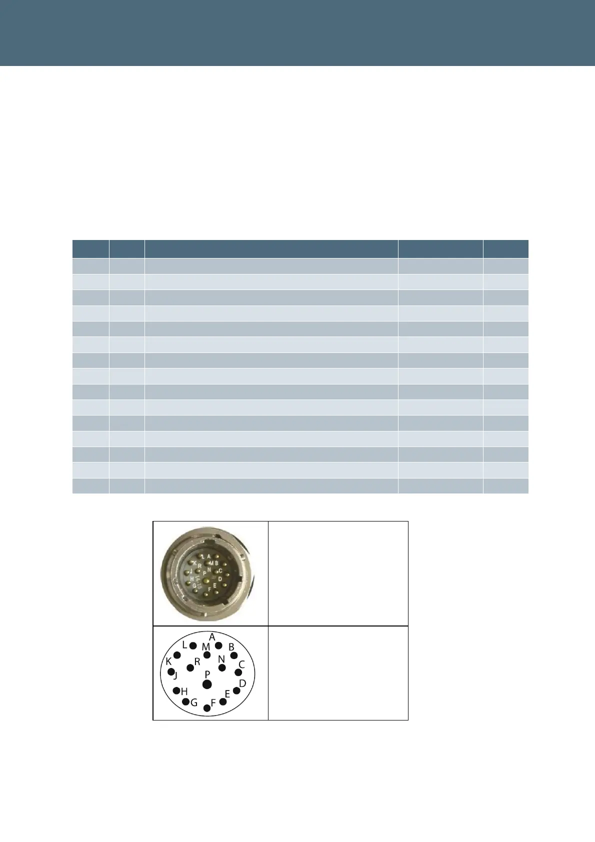
MAIN connector on Sicore
unit (view from mating
side )
15-way male circular
connector (ITT Cannon)
Connector pins, view from
mating side
Figure 9 – Main Connector Pin Arrangement
 Loading...