Mounting and connecting
3.5 Wiring and circuit diagram
CPU 1516pro-2 PN (6ES7516-2PN00-0AB0)
Operating Instructions, 09/2016, A5E35873416-AA
33
Wiring and circuit diagram
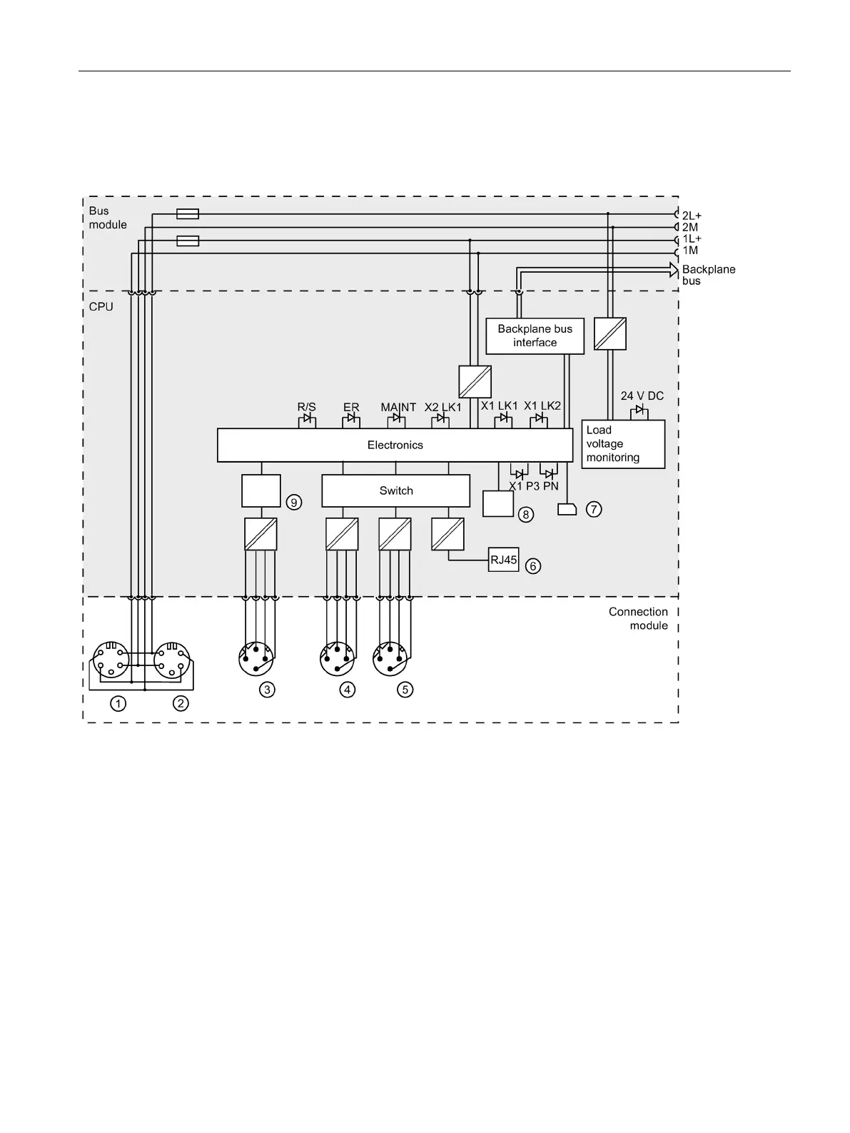
The figure below shows the wiring and circuit diagram of the CPU 1516pro-2 PN.
Infeed of electronics/encoder supply 1L+ and load voltage supply 2L+ (X3)
Loop-through of electronics/encoder supply 1L+ and load voltage supply 2L+ (X4)
PROFINET interface X2 Port 1 (X2 P1)
LED diagnostic status (red)
PROFINET interface X1 Port 1 (X1 P1 R)
LED diagnostic status (yellow)
PROFINET interface X1 Port 2 (X1 P2 R)
LED load voltage supply (green)
PROFINET interface X1 Port 3 (X1 P3)
PROFINET LEDs (green)
X2 P1
LED operating mode (green)
Figure 3-4 Wiring and circuit diagram