Configuring
4.2 Configuring the CPU
CPU 1516pro-2 PN (6ES7516-2PN00-0AB0)
Operating Instructions, 09/2016, A5E35873416-AA
41
Addressing analog electronic modules
Introduction
The addressing of analog electronic modules is described below. You need the addresses of
the channels of the analog electronic module in the user program.
The address of an analog channel is always a word address. The channel address depends
on the module start address. The channel addresses are automatically assigned during
configuration in STEP 7. Based on the module start addresses, the assignment of the
channel addresses occurs in increasing sequence (in the following figure, the module start
address is 256).
When you insert an analog electronic module into a free slot, STEP 7 assigns a default
address. You can change the proposed default address in STEP 7.
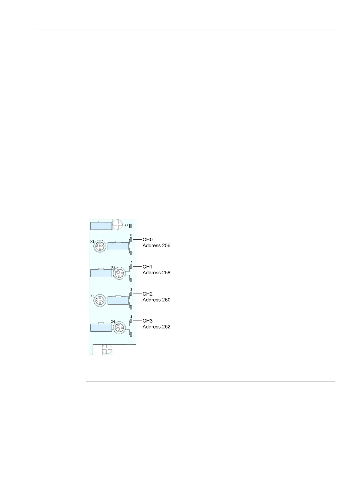
Example of the assignment of addresses to channels (analog electronic module)
The following figure shows how the addresses of the individual channels arise using the
analog electronic module 4 AI RTD High Feature as an example.
Figure 4-6 Example of the assignment of addresses to channels (analog electronic module)
Note
You can assign symbolic names to the addresses at the following locations in STEP 7:
PLC tag table
Properties of the module in the "IO Tags" tab.