Connection Diagrams
B-3
FM 351 Positioning Module
C79000-G7076-C351-02
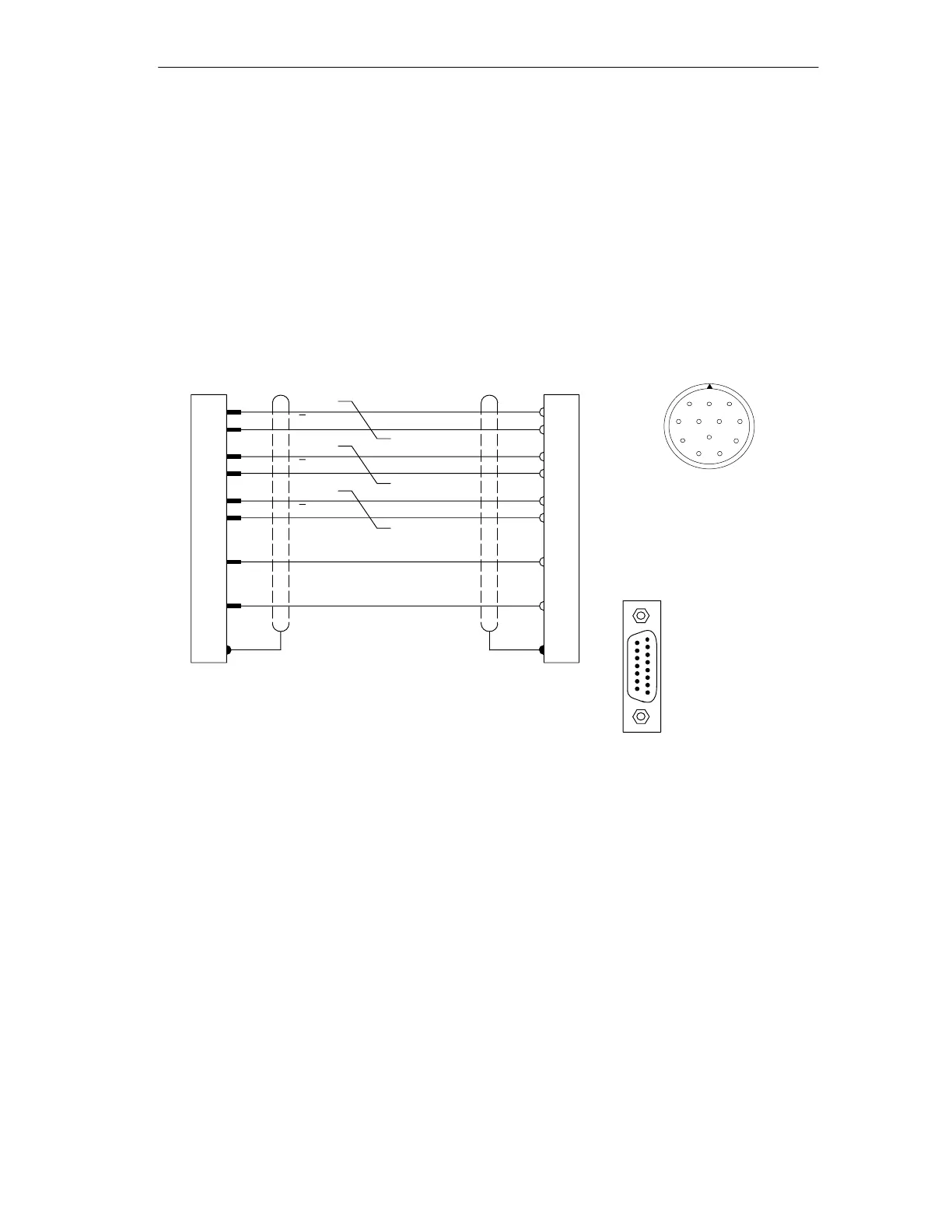
B.2 Connection Diagram for Incremental Encoder Siemens 6FX
2001-2 (Up=24V; RS 422)
Connection Diagram
The following illustration shows the connecting diagram for the incremental
encoder Siemens 6FX 2001-2(U
p
=24 V; RS 422):
Wire 4 2 0.5 mm
2
Twisted pair
Round 12-pin socket
Siemens 6FX 2003-0CE12
solder side
1
2
3
45
6
7
8
9
10
11
12
15
14
13
12
10
11
7
5
5
6
8
1
3
4
10*
12**
11*
2**
A
A
B
B
N
N
FM 351 Encoder
Ground
+24 V
Shield on
housing
Shield on
housing
15-pin
sub-D male
connector
Solder side metallized
casing secured by
screws
6FC9 341-1HC
15
9
8
1
* Pins 10 and 11 are jumpered internally.
** Pins 2 and 12 are jumpered internally.

 Loading...


