Wiring the FM 351
4-7
FM 351 Positioning Module
C79000-G7076-C351-02
4.4 Wiring the Power Unit
Power Unit
The power unit (for example a simple contactor combination) is connected to the
digital outputs of the FM 351 and controls the motor.
Contactor Circuit
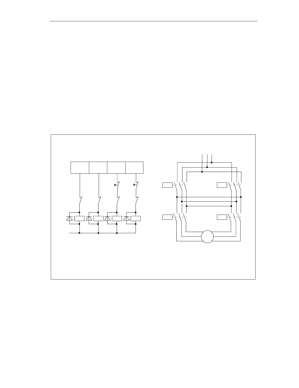
Figure 4-3 shows the control and load current circuits of a power unit.
The functions of the digital outputs correspond to control mode 1
(see Section 8.3, page 8-6).
Load circuitControl circuit
1Q0
1Q1
1Q2
1Q3
Digital outputs on FM 351
M
K3
K4
K2
K1
K1
K2
K4
K3
K1 = direction plus
K2 = direction minus
K3 = rapid speed
K4 = creep speed
E1
E2
E1 = hardware limit switch minus
E2 = hardware limit switch plus
K1
K3
K2
K4
M
Pole-changing motor
L1 L2 L3
NC
contact
of
Figure 4-3 Contactor Circuit
How the Contactor Circuit Works
Contactors K1 and K2 control the direction of the motor. The contactors are
interlocked by the normally closed contacts K2 and K1. The hardware limit
switches E1 and E2 are the limit switches minus/plus. If the axis travels beyond
these limit switches, the motor (direction) is turned off.
The contactors K3 and K4 switch the motor from rapid to creep speed. The
contactors are interlocked by the normally closed contacts K4 and K3.