Connection Diagrams
B-4
FM 351 Positioning Module
C79000-G7076-C351-02
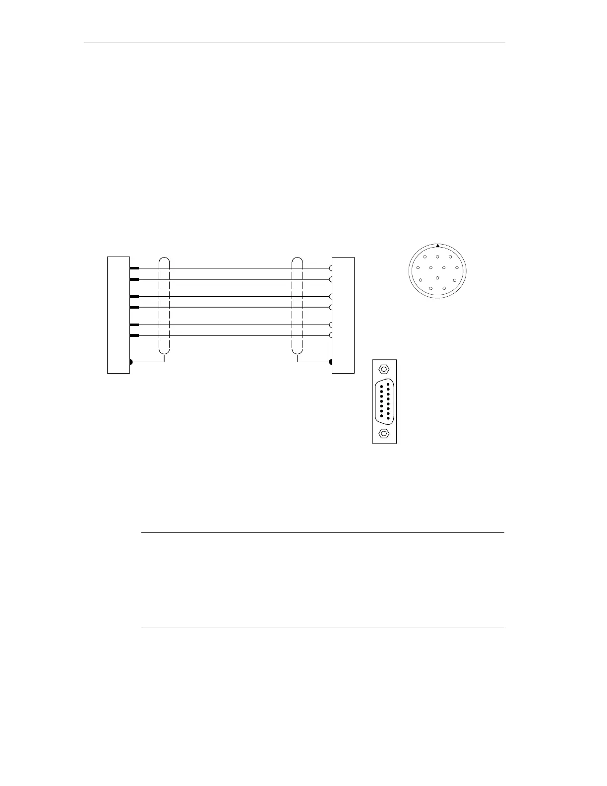
B.3 Connection Diagram for Incremental Encoder Siemens 6FX
2001-4 (Up=24V; HTL)
Connection Diagram
The following illustration shows the connecting diagram for the incremental
encoder Siemens 6FX 2001-4(Up=24 V; HTL):
Round 12-pin socket
Siemens 6FX 2003-0CE12
solder side
1
2
3
45
6
7
8
9
10
11
12
1
4
8
7
5
9
A*
B*
N*
FM 351 Encoder
Ground
Shield on
housing
Shield on
housing
Wire 4 2 0.5 mm
2
+24 V
RE
5
8
3
10*
12**
11*
15-pin
sub-D male
connector
Solder side metallized
casing secured by
screws
6FC9 341-1HC
15
9
8
1
2**
* Pins 10 and 11 are jumpered internally.
** Pins 2 and 12 are jumpered internally.
Note
If you would like to connect an incremental encoder from another manufacturer in
a push-pull configuration (current sourcing/sinking), then you must observe the
following:
• Current sourcing: Connect RE (9) to ground (7).
• Current sinking: Connect RE (9) to +24 V (5).

 Loading...


