Wiring the FM 351
4-3
FM 351 Positioning Module
C79000-G7076-C351-02
4.2 Connecting the Encoders
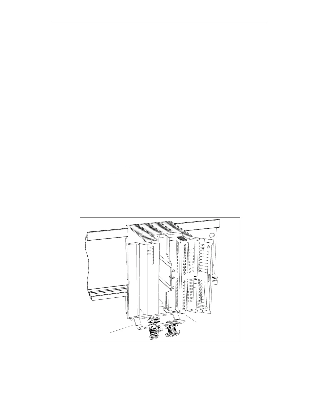
Shield Contact Element
Using the shield contact element, you can connect all shielded cables with ground
simply and easily making use of the direct connection between the shield contact
element and the rail. For more detailed information, refer to the manual
S7-300
Programmable Controller, Hardware and Installation
.
Procedure
Follow the steps outlined below to connect the encoder:
1. Connect the cable to the encoder.
With some encoders it may be necessary to assemble the cable (at the encoder
end) according to the manufacturer’s specifications.
2. The encoder cables must be shielded.
3. The leads A and A, B and B, N and N of an incremental encoder or the leads
DAT and DAT, CLS and CLS of an absolute encoder must be twisted in pairs.
4. Open the front panel and plug the sub D connector into the FM 351.
5. Secure the connector with the knurled screws. Close the front panel.
6. Remove the insulation from the cable and clamp the cable shield into the shield
contact element. Use shield clamps.
Front Connector (X1)
Shield contact element
Figure 4-2 Location of the Shield Contact Element