Machine Data and Incremental Dimensions
8-14
FM 351 Positioning Module
C79000-G7076-C351-02
Address Name Data
Type
Initial Value Description
64.0
68.0
SSW_STRT
SSW_END
DINT
DINT
L#–100000000
L#100000000
Software limit switch start
Software limit switch end
Range:
• –1 000 000 000 m to 1 000 000 000 m at
a resolution of 1 m/pulse
• –100 000 000 m to 100 000 000m
at a resolution of < 1 m/pulse
These axis data are used only for a linear axis.
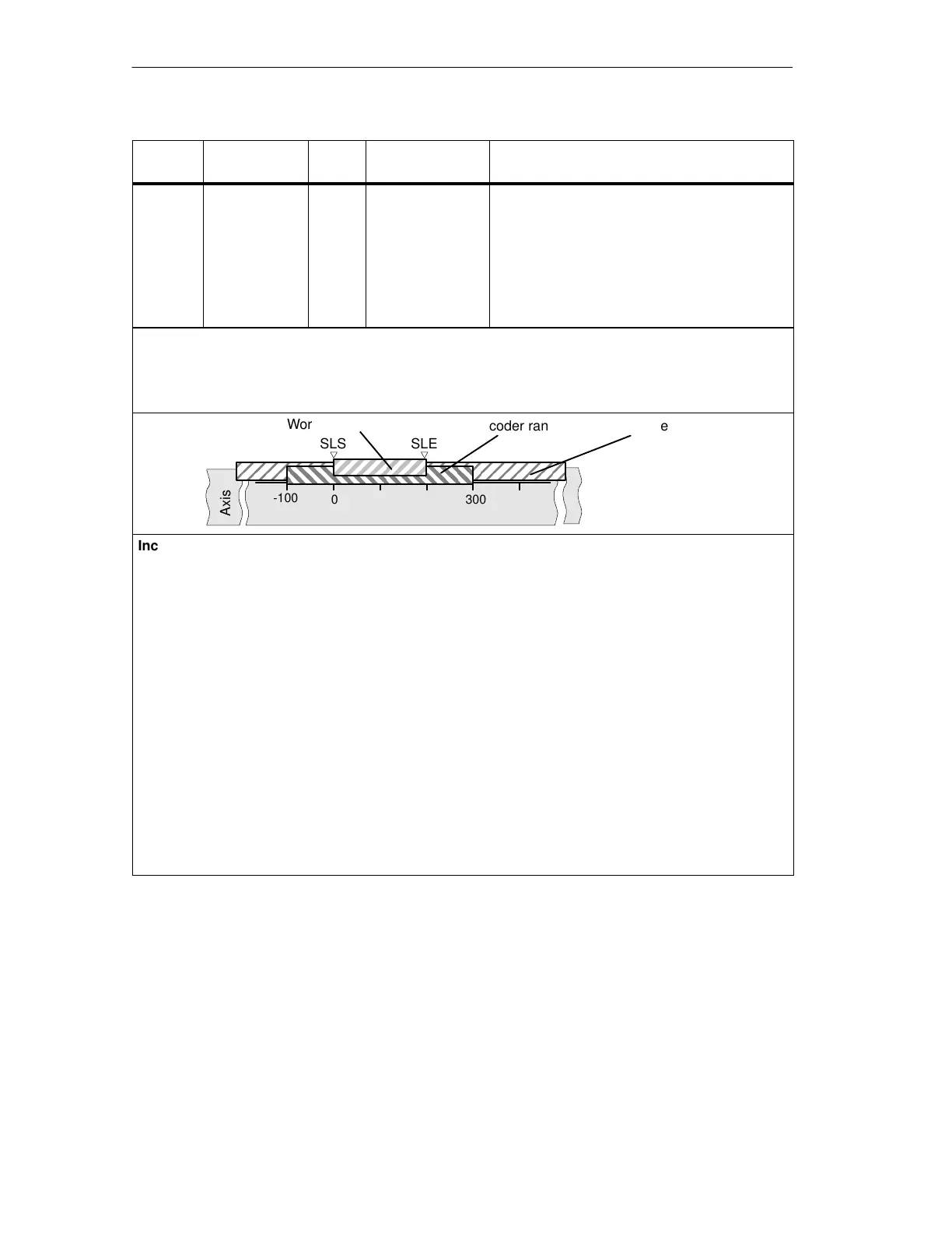
The software limit switches are monitored when the axis is synchronized. The range set by the software
end limit switch is known as the working range.
The start software limit switch (SLS) must always be less than the end software limit switch (SLE).
0 300
-100
Axis
Working range
Encoder range Travel range
SLS SLE
Incremental encoders
Initially, the axis is not synchronized after each FM 351 startup. The set software limit switches are only
monitored after synchronization.
Absolute encoder (SSI)
The axis is synchronized once the FM 351 has received a complete, error-free frame for the relevant
channel. The software limit switches are monitored from this point in time.
The absolute encoder must cover at least the working range including the software limit switches.
Relationship: working range, encoder range, travel range
• The “working range” is the range you specify for your task using the software limit switches.
• The “encoder range” is the range covered by the encoder. With a linear axis, this is placed
symmetrically over the working range by the module; in other words, the module shifts the encoder
range so that the distances between the software limit switches and the ends of the encoder range
are the same (see figure).
• The “travel range” is the range of values that can be processed by the FM 351. It is dependent on the
resolution.
 Loading...


