Detailed descriptions
16.4 I/O Address Areas
SIMATIC IPC427C
140 Operating Instructions, 04/2009, A5E02414743-01
16.4.5 Output register LED 1 / 2 (read/write, address 404Eh)
Meaning of the bits
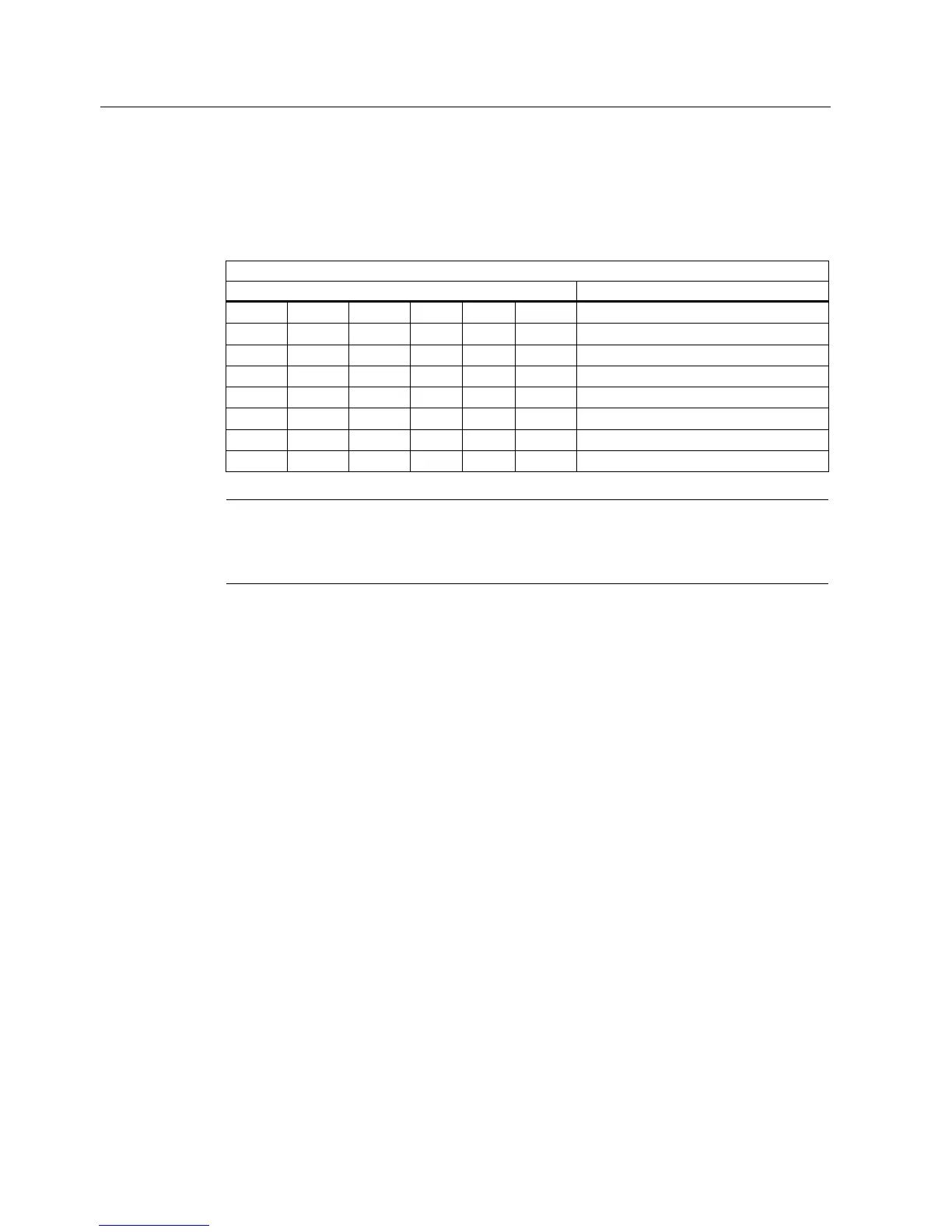
Output register LED 1 / 2 (read/write address 404Eh)
Bits
15 14 13 - 8 7 6 5 - 0
1 1 LED L1 / SF dark (default)
1 0 LED L1 / SF lights yellow
0 1 LED L1 / SF lights red (= group fault)
1 1 LED L2 / R/S dark (default)
1 0 LED L2 / R/S lights yellow (= STOP)
0 1 LED L2 / R/S lights green (= RUN)
xxxxxx xxxxxx Reserved (read/write)
Note
The L1 and L2 LEDs indicate by flashing alternatively yellow the progress of the BIOS self-
test during the device startup. When the BIOS self-test is completed, the L1 and L2 LEDs go
dark.