Description
3.5 Design
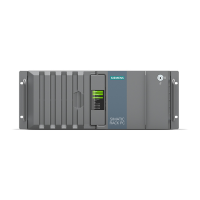
SIMATIC IPC427C
18 Operating Instructions, 04/2009, A5E02414743-01
3.5.2 Connection components
Ports and power supply
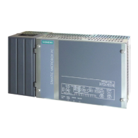
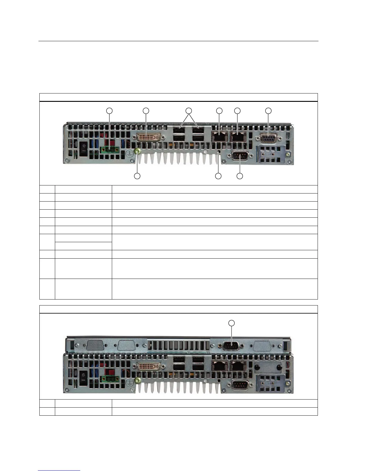
Location of connection elements (version with PROFIBUS or CAN)
Pos Name Description
① 24 VDC Connection for a 24 V DC power supply
② DVI/VGA DVI/VGA connection for CRT or LCD monitor with DVI interface
③ USB 4 USB 2.0 connections, high-speed / low current
④ PN/IND. ETHERNET RJ45 Ethernet connection 1 (exclusive PCI interrupt) for 10/100/1000 Mbps
⑤ PN/IND. ETHERNET RJ45 Ethernet connection 2 (shared PCI interrupt) for 10/100/1000 Mbps
PROFIBUS DP/MPI ⑥
CAN fieldbus
PROFIBUS DP/MPI interface (RS 485 isolated), 9-pin Cannon socket or CAN fieldbus
(on request)
⑦ COM1 Serial port (RS232) 9-pin Cannon connector
⑧ USB strain-relief
fastener
The USB strain relief must be fastened to the device enclosure with an oval-head screw
(M4 thread). The USB cables can be fastened to the strain-relief assembly with a cable
tie.
⑨ PE terminal The PE terminal (M4 thread) must be connected to the protective ground conductor of the
plant, in which the device is to be installed. The minimum conductor cross-section may not
be less than 2,5 mm
2
.
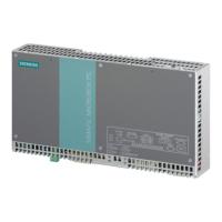
Location of the connection elements (second COM interface)
Pos Designation Description
① COM2 Serial port (RS232) 9-pin Cannon connector