Description
16 REVISION 02 * DESCRIPTION SIMOSEC * 832-6063.0
8.4 Protection and control equipment
Protection and control equipment is supplied according to the customer’s specifications.
The devices are installed in the standard low voltage compartment (item 28,
see Fig. 3, page 9). For details please refer to the schematic diagrams for the
switchgear.
Mimic diagram The mimic diagram on the control panel corresponds with the switching functions of the
panel.
Local-remote switch
(option)
The local-remote switch determines the location from which the three-position switch
can be motor-operated.
The local-remote switch latches (non-spring-return) in the corresponding switch position.
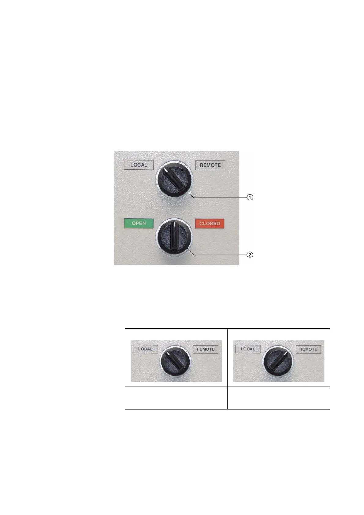
Fig. 12: Control panel section
a
Local-remote switch, maintained-
contact (non-spring-return)
s
Momentary-contact rotary control
switch (spring-return)
LOCAL position:
Local operation
REMOTE position:
Remote operation from the
control room/monitoring station