832-6063.0 * DESCRIPTION SIMOSEC * REVISION 02 9
Description
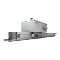
7 Panel versions
Fig. 2: Cable switch panel CS
(shown with main bus in the middle)
Fig. 3: Fuse switch panel FS
(shown with main bus on top)
1 Sockets for capacitive voltage detection system 15 Gas-insulated vessel for switching device
2 Manual operation for the mechanism of the load-break /
disconnecting function
16 Bushing-type insulator for feeder
3 Indicator “Fuse intact / Fuse blown” 17 Cable connection
4 Switch position indicator for load-break and for grounding function
"CLOSED-OPEN-GROUNDED"
18 Cable termination (not in scope of supply)
5 Manual operation for the mechanism of the grounding function 19 Cable connection compartment
6 Sockets for capacitive voltage detection system 20 Three-position switch
7 Insulating cap on bus bar (for > 15 kV) 21 Grounding bus bar
8 Bus bar 22 Spring-operated mechanism for three-position switch
9 Bushing-type insulator for bus bar 23 Grounding connection (for location see dimension drawings)
10 “Ready-for-service” indicator for switching device 24 Option: Local-remote switch for the motor operating mechanism of the
three-position switch
11 Interlocking lever of cable compartment cover
(with three-position switch)
25 Option: Momentary-contact rotary control switch "CLOSED - OPEN" for
motor operating mechanism for three-position switch
12 Pressure relief device for switching device 26 Option: HV HRC (current limiting) fuse
13 Locking device for three-position switch 27 Post insulator
14 Cable compartment cover/ door 28 Low voltage compartment