832-6063.0 * DESCRIPTION SIMOSEC * REVISION 02 21
Description
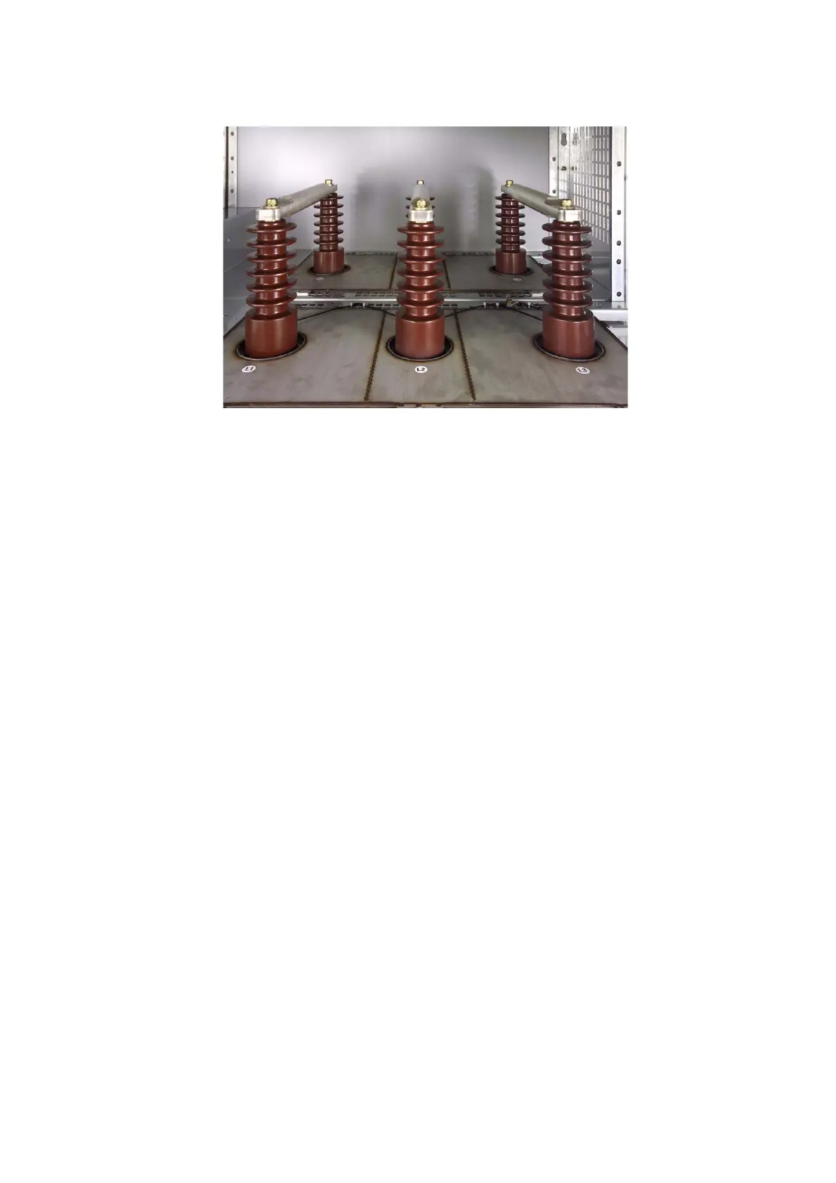
8.7 Bus bars
Fig. 16: Bus bar compartment (bus with heat shrink insulation and insulating caps for >15 kV)
Features
• Metal-enclosed bus bar compartment
• Bus bars bolted from panel to panel
• Versions:
-1200A
- heat shrink insulation (option)
- insulating caps (standard for over 15 kV)
8.8 Cable connection
Features
• Cable termination points are arranged one behind the other
• Uniform cable connection height per panel (see dimension drawings)
• With cable bracket or cable clamps and grounding points for cable shields
• Access to the cable connection compartment only when feeder has been grounded
Features for cable terminal
• For thermoplastic-insulated cables
• For paper-insulated mass-impregnated cables
• For connection cross-sections (cable size)* up to 300 mm
2
(600 kcmil)
• Cable bottom entry (from below) - standard
• Cable top entry (from above) - optional
Applicable cable types are described in Section "Cable terminations" (see Description,
Page 34).
Installation of high voltage cables is described specifically for each panel in the operating
Instructions (see “Connecting high voltage cables” on page 53).
* Larger connection cross-sections on request.