Do you have a question about the Siemens SIVACON 8PS and is the answer not in the manual?
Outlines the essential information and topics covered in the documentation.
Summarizes the structure and contents of the documentation by chapter.
Identifies the intended audience for this documentation.
Lists additional information material available for consultation.
Lists applicable standards for the SIVACON 8PS busbar trunking system.
Details building authority certifications and inspection certificates.
Presents national and marine classification society approvals.
Introduces various Siemens busbar trunking systems like CD-K, BD01, BD2, LD, LX, LR.
Presents performance data overview for CD-K, BD01, BD2, LD, LX, LR systems.
Details the application areas for LX, LD, and LR systems in public and industrial buildings.
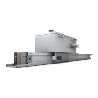
Provides an overview of the LX busbar trunking system's components and features.
Explains the different system sizes and the structure of single and double systems.
Details the eight different conductor configurations available for the LX busbar system.
Discusses important properties of N and PE conductor cross-sections and clean earth.
Provides guidelines for selecting and ordering products, including metal supplements and dimensions.
Explains how type codes are used to define basic components of the LX system.
Contains tables for selecting straight trunking units, junction units, feeder units, tap-off units, etc.
Details how to make secure joints using joint blocks and screw heads.
Explains standard installation and custom length insertion for horizontal busbar runs.
Specifies minimum wall and ceiling distances for horizontal and vertical runs.
Covers positioning and installation of fire barriers in walls and ceilings.
Describes how to secure horizontal busbar runs with fixing brackets.
Explains the dimensioning and selection of fixing brackets for vertical installation.
Covers type determination for straight trunking units, junction units, feeder units, and tap-off units.
Details planning horizontal and vertical busbar runs, including expansion compensation.
Provides general technical specifications for LX systems, including standards and ambient conditions.
Details electrical and mechanical data for LXA..30 aluminium trunking units.
Details electrical and mechanical data for LXA..41 aluminium trunking units.
Details electrical and mechanical data for LXA..51 aluminium trunking units.
Details electrical and mechanical data for LXA..52 aluminium trunking units.
Details electrical and mechanical data for LXA..61 aluminium trunking units.
Details electrical and mechanical data for LXC..30 copper trunking units.
Details electrical and mechanical data for LXC..41 copper trunking units.
Details electrical and mechanical data for LXC..51 copper trunking units.
Details electrical and mechanical data for LXC..52 copper trunking units.
Details electrical and mechanical data for LXC..53 copper trunking units.
Details electrical and mechanical data for LXC..54 copper trunking units.
Details electrical and mechanical data for LXC..61 copper trunking units.
Details electrical and mechanical data for LXC..62 copper trunking units.
Provides fire load values for trunking units without tap-off points.
Lists fixing distances for mechanical loads with horizontal installation.
Specifies conductor cross sections for connecting to non-Siemens distribution boards.
Provides technical data for tap-off units with circuit breakers and fuse switch disconnectors.
Shows dimension drawings for straight trunking units with and without tap-off points and expansion compensation.
Provides dimension drawings for various junction units like elbows and knees.
Details dimension drawings for universal busbar connection units and cable feeder units.
Shows dimension drawings for tap-off units with circuit breakers and fuse switch disconnectors.
Illustrates dimensions for joint blocks, fixing brackets, and end caps.
Presents the circuit diagram for a 3-pole tap-off unit with a circuit breaker.
Presents the circuit diagram for a 4-pole tap-off unit with a circuit breaker.
| Brand | Siemens |
|---|---|
| Model | SIVACON 8PS |
| Category | Power distribution unit |
| Language | English |