Dimension drawings
8.3 Feeder units
SIVACON 8PS - Configuring with LX system
Configuration Manual, 10/2011, A5E02194899-02
167
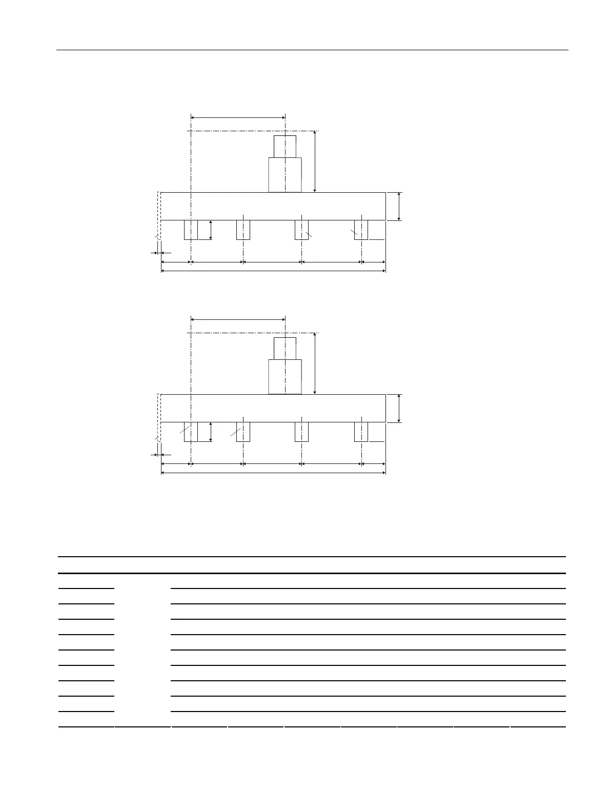
8.3.1.4 Universal busbar connection unit AS1 with T tap-off unit
//
,
D
3(11
E E
S
S
S
3(
F
K
K
Figure 8-17 LX.....-AS1-T(+LX-.A)/(+LX-.C)
//
,
D
3(11
E E
S
S
S
3(
F
K
K
1)
Reference dimension for configuring = centre of joint block to centre of 1st connection tag
((PEN(N) at front).
More detailed information: See Chapter Feeder units (Page 164).
2)
Total length l of the connection unit is the sum of the configured connection tag distances.
Figure 8-18 LX.....-AS1-T(+LX-.B)/(+LX-.D)
System a b1 b2 c h1 h2 p min. p max.
LXA(C)01 143 143 213 137 96.5 115 400
LXA(C)02 143 143 213 137 96.5 115 400
LXA(C)03 143 143 188 162 96.5 135 400
LXA(C)04 143 143 188 162 96.5 135 400
LXA(C)05 143 143 293 207 96.5 135 400
LXA(C)06 143 143 213 287 96.5 155 400
LXA(C)07 143 143 213 287 96.5 155 400
LXA(C)08 203 203 361 439 96.5 275 400
LXA(C)09 203 203 201 599 96.5 275 400
LXA(C)10
1.5 x p
203 203 201 599 96.5 275 400
 Loading...


