EasyManua.ls Logo

Siemens SIMOTICS S-1FL6 - Page 34

Siemens SIMOTICS S-1FL6
118 pages
To Next Page IconTo Next Page
To Previous Page IconTo Previous Page
Loading...
Getting Started
34 A5E37208904-003, 04/2017
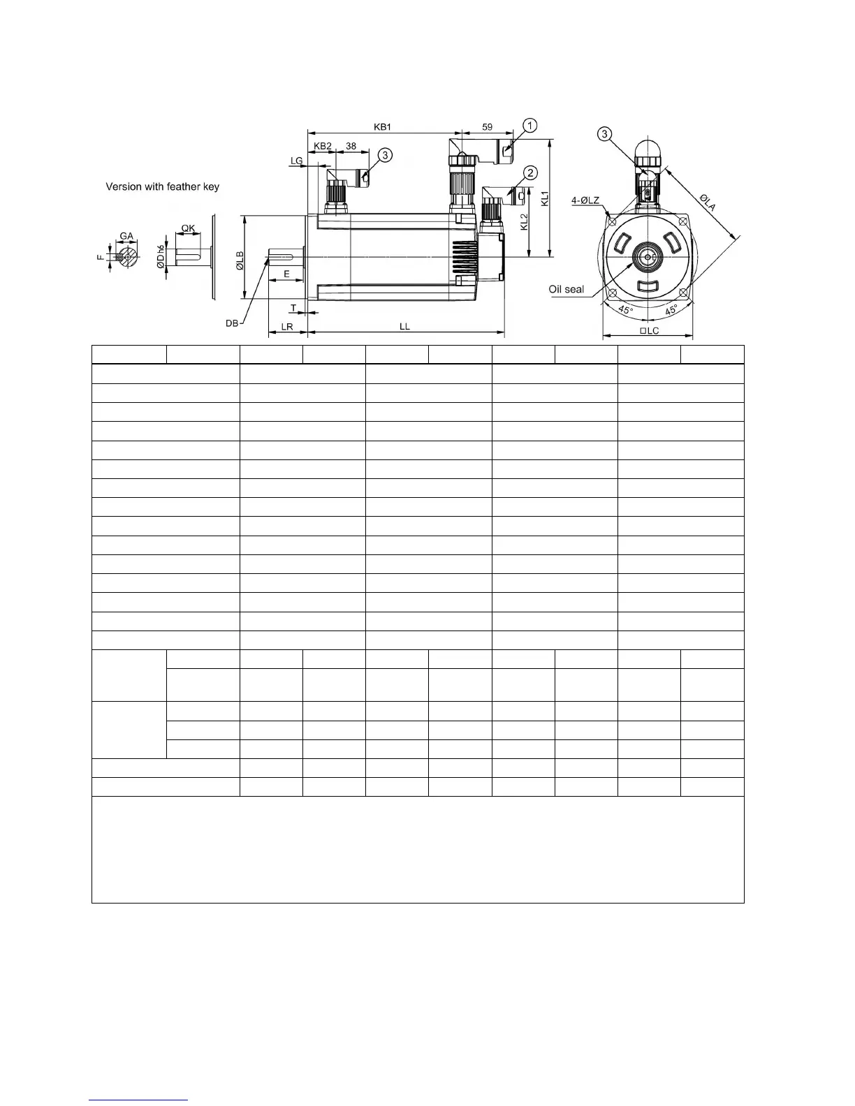
Low inertia servo motor, shaft height: 50 mm
Type
1FL60...
22
24
32
34
42
44
52
54
Shaft height
20
30
40
50
LC
40
60
80
100
LA
46
70
90
115
LZ
4.5
5.5
7
9
LB
30 - 0.02
50 - 0.03
70 - 0.03
95 - 0.03
LH
40
50
60
-
LR
25
31
35
45
T
2.5 - 0.2
3 - 0.2
3 - 0.3
3 - 0.3
LG
6
8
8
12
D
8 - 0.009 14 - 0.011 19 - 0.013 19 - 0.013
DB
M3 × 8
M4 × 15
M6 × 16
M6 × 16
E
22 26 30 40
QK
17.5
22.5
28
28
GA
9
16
21.5
21.5
F
3
5
6
6
Without
brake
LL
86
106
98
123
139
158.8
192
216
KB1
- - - - - - 143.5 167.5
With brake
LL
119
139
132.5
157.5
178.3
198.1
226
250
KB1
-
-
-
-
-
-
177.5
201.5
KB2
-
-
-
-
-
-
32.5
32.5
KL1
-
-
-
-
-
-
135
135
KL2
-
-
-
-
-
-
80
80
Power cable connector,
Incremental encoder cable connector,
Brake cable connector. These connectors
should be ordered separately. For more information about the order information of the connectors, see the SINAMICS
V90, SIMOTICS S-1FL6 Operating Instructions.
For the low inertia motor with shaft-height of 50 mm, the boundary dimensions of encoder connector−
and brake
connector−
are the same.
For the low inertia motor with shaft-height of 20 mm, only two screws are needed to mount the flange.

Other manuals for Siemens SIMOTICS S-1FL6

Related product manuals