Mechanical mounting
6.4 Installing the stator in the spindle housing
SIMOTICS M-1FE2 built-in motors
Hardware Installation Manual, 04/2020, A5E50074509B AA
117
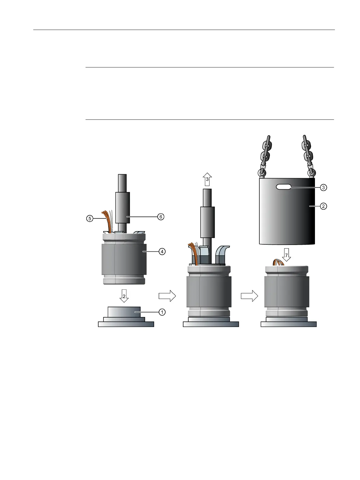
Procedure when mounting the spindle housing over the stator
Note
Different shape
The spindle housing
② can also represent a cooling jacket provided additionally by the
customer. The shape of the component may differ from the illustration. The shapes of
the
-stop ① and of the internal mandrel ⑥ depend on the shape of the components
and may differ from those in the illustration.
Stator without cooling jacket
Spindle housing/cooling jacket
Internal tensioning spindle
Figure 6-17 Mounting the spindle housing over the stator without cooling jacket, steps 2, 3 and 7
The numbered arrows visualize the following steps with the same numbering.
1. Clean contaminants and chips from the subassemblies
② and ④.
2. Place the stator on the mounting support.
3. Remove the internal tensioning spindle from the stator.

 Loading...


