Connection
7.2 Electrical connection
SIMOTICS M-1FE2 built-in motors
Hardware Installation Manual, 04/2020, A5E50074509B AA
155
Preconditions
The initial commissioning has been completed.
The following conditions must be true:
● 2 motor data sets (MDS), p0130 = 2
● 2 drive data sets (DDS), p0180 = 2
● 2 digital outputs to control the auxiliary contactors
● 2 digital inputs to monitor the auxiliary contactors
● 1 free speed setpoint monitor (p2155)
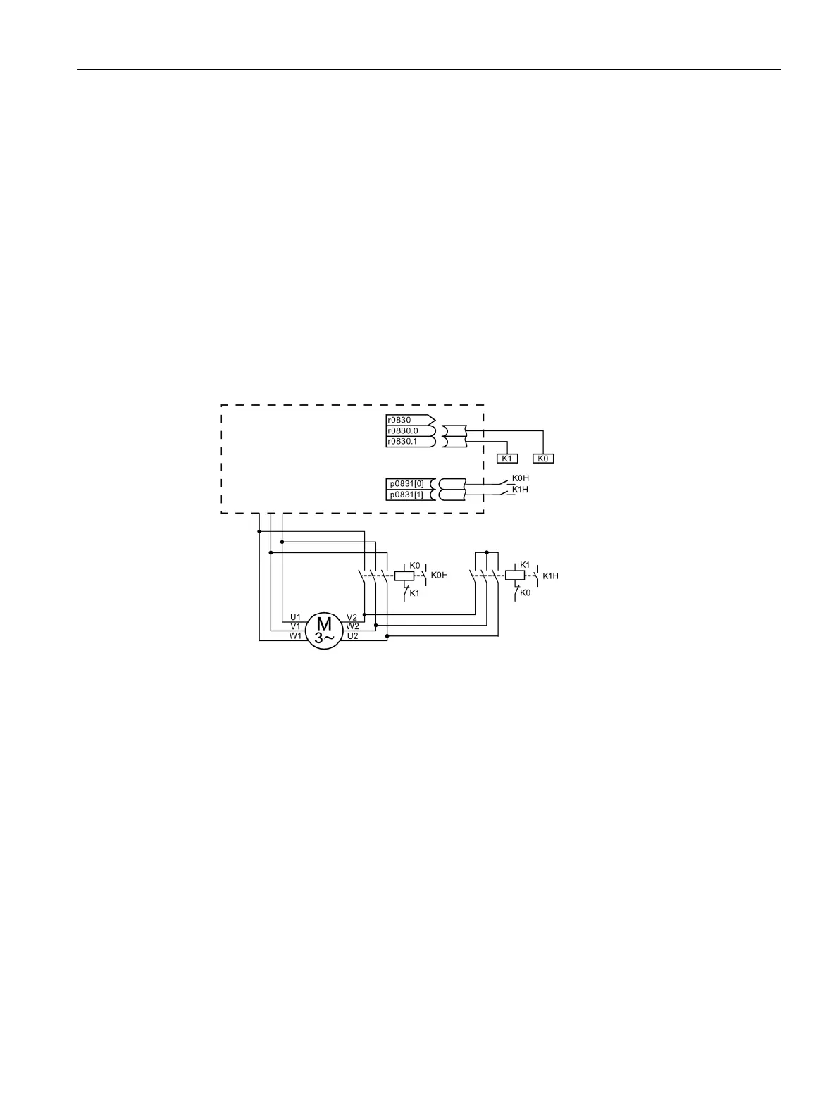
● 2 auxiliary contactors with auxiliary contacts (1 NO contact)
● 2 motor contactors with positively driven auxiliary contacts (1 NC contact, 1 NO contact)
● 1 motor, 1 control unit, 1 infeed, and 1 Motor Module
Figure 7-10 Example of star-delta changeover

 Loading...


