EasyManuals Logo

Siemens SIMOTICS Series Hardware Installation Manual

Siemens SIMOTICS Series
214 pages
To Next Page IconTo Next Page
To Previous Page IconTo Previous Page
Page #31 background imageLoading...
Page #31 background image
Description
3.3 Technical features and system requirements for built-in motors
SIMOTICS M-1FE2 built-in motors
Hardware Installation Manual, 04/2020, A5E50074509B AA
29
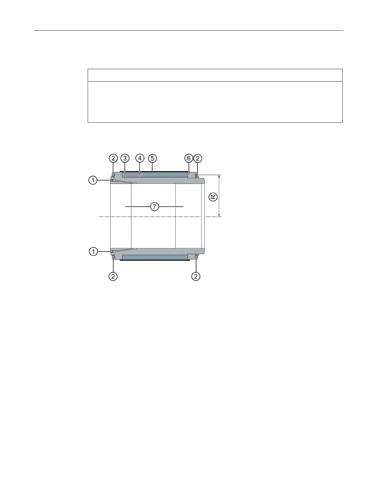
Design of the rotor core (APM)
NOTICE
Damage to the rotor bandage due to premature removal of the protection foil
A rotor bandage with a foil is provided for transport protection.
Remove the protective foil only immediately before assembly.
Check the bandage for damage.
APM rotor core
Pressure oil connection with grub screw
Encircling groove for deployable balancing elements
Sleeve
Rotor core
Bandage (composite fiber)
Balancing disk
Step press fit
R
Balancing radius
Figure 3-3 APM rotor core design

Table of Contents

Other manuals for Siemens SIMOTICS Series

Questions and Answers:

Question and Answer IconNeed help?

Do you have a question about the Siemens SIMOTICS Series and is the answer not in the manual?

Siemens SIMOTICS Series Specifications

General IconGeneral
Product brand nameSIEMENS
Product designationSIMOTICS
Efficiency ClassIE1, IE2, IE3, IE4
Ambient Temperature+60°C
AltitudeUp to 4000 m
Frame Size63 to 355
Protection ClassIP55, IP56, IP65

Related product manuals