Description
3.3 Technical features and system requirements for built-in motors
SIMOTICS M-1FE2 built-in motors
Hardware Installation Manual, 04/2020, A5E50074509B AA
37
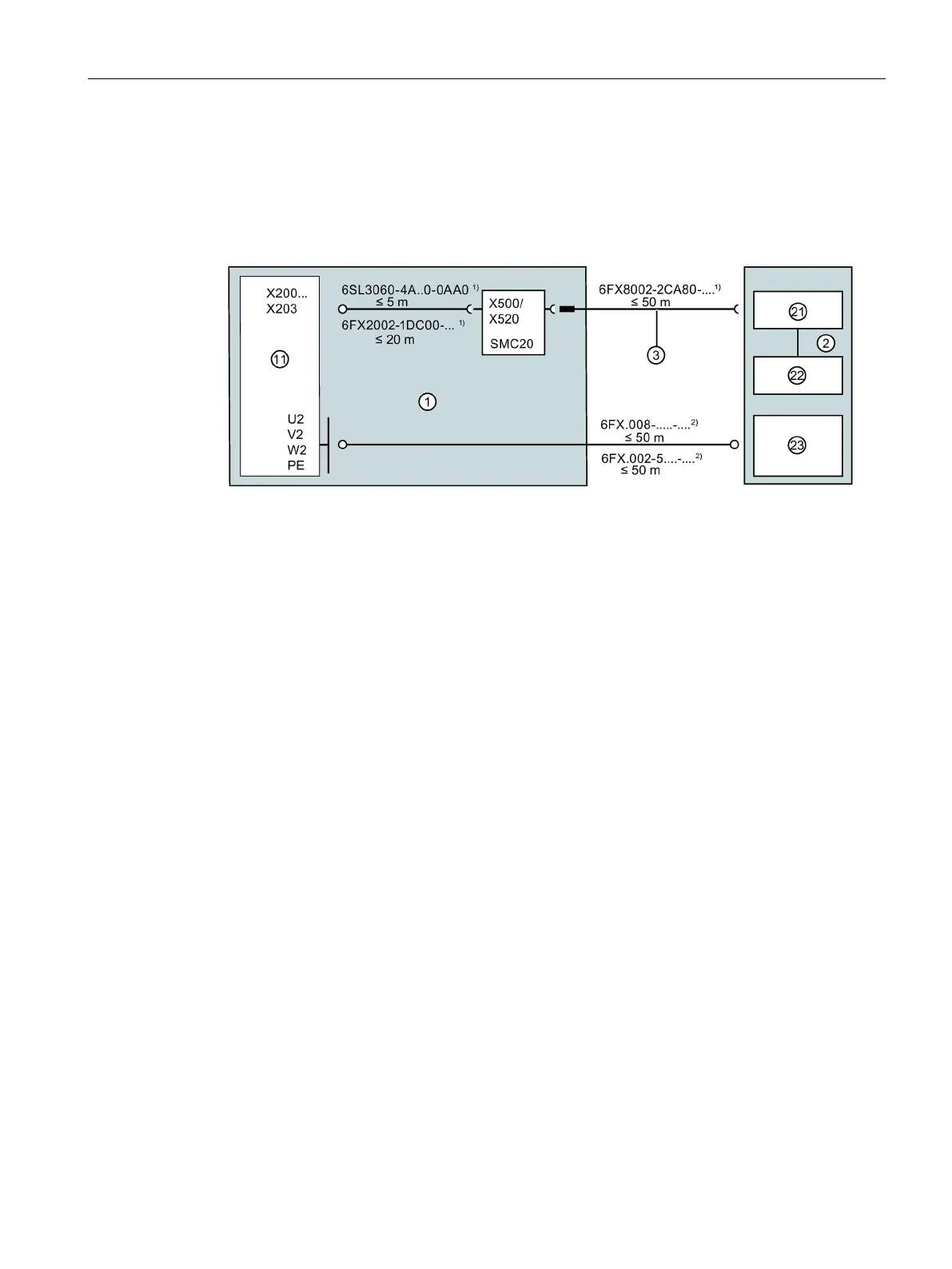
Versions of the system integration for asynchronous motors
The following diagrams show the possible system integration configurations of the 1FE2 in
asynchronous version.
General rule: Motor with standard protection, integrated into the system via SMC20
1)
Article numbers for prefabricated
MOTION-CONNECT signal cables, M23
connector size
2)
Article numbers for prefabricated
MOTION-CONNECT power cables
≲ 25 m in the case of star-delta changeover in
Pt1000 temperature sensor
11 SINAMICS S120 Motor Modules,
Booksize format, DRIVE CLiQ communi-
23 1FE2 winding, connection via terminal box
2 1FE2 built-in motor
3 Signal cable for encoder and temperature sen-
sor,
17-pin M23 round connector
21 Incremental encoder sin/cos 1 Vpp or
EnDat 2.1 absolute encoder

 Loading...


