Mechanical mounting
6.3 Installing/removing the rotor
SIMOTICS M-1FE2 built-in motors
Hardware Installation Manual, 04/2020, A5E50074509B AA
95
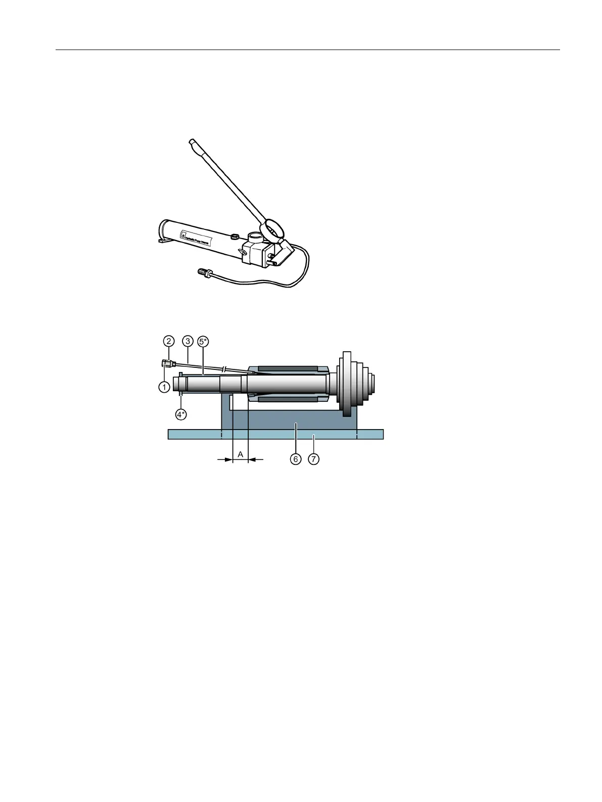
Devices and materials for relieving stress on the rotor with sleeve after installation
● Oil-pressure hand pump with manometer for relieving the stress on, or removing the rotor
with sleeve for "oil press fit" device version
Figure 6-5 Oil pressure hand pump e.g. type SKF 1077454
● Equipment for relieving stress on the rotor or removing it
Connection hydraulic hand pump
Extension tube, e.g. type SKF1077453
Slotted nut (only for relieving stress)
Spacer sleeve (only for relieving stress)
1)
Tray for catching oil made from aluminum, for example
1)
Dimension for the axial relative movement for removal of the synchronous version, 90 mm
1)
In the synchronous version these parts must be non-magnetic.
Figure 6-6 Equipment for relieving stress on the rotor with sleeve and for removing it
● Pressure oil for relieving stress, e.g. SKF LHMF 300 (viscosity 300 mm²/s at 20° C)
● Pressure oil for removal, e.g. SKF LHDF 900 (viscosity 900 mm²/s at 20° C)

 Loading...


