Accessories
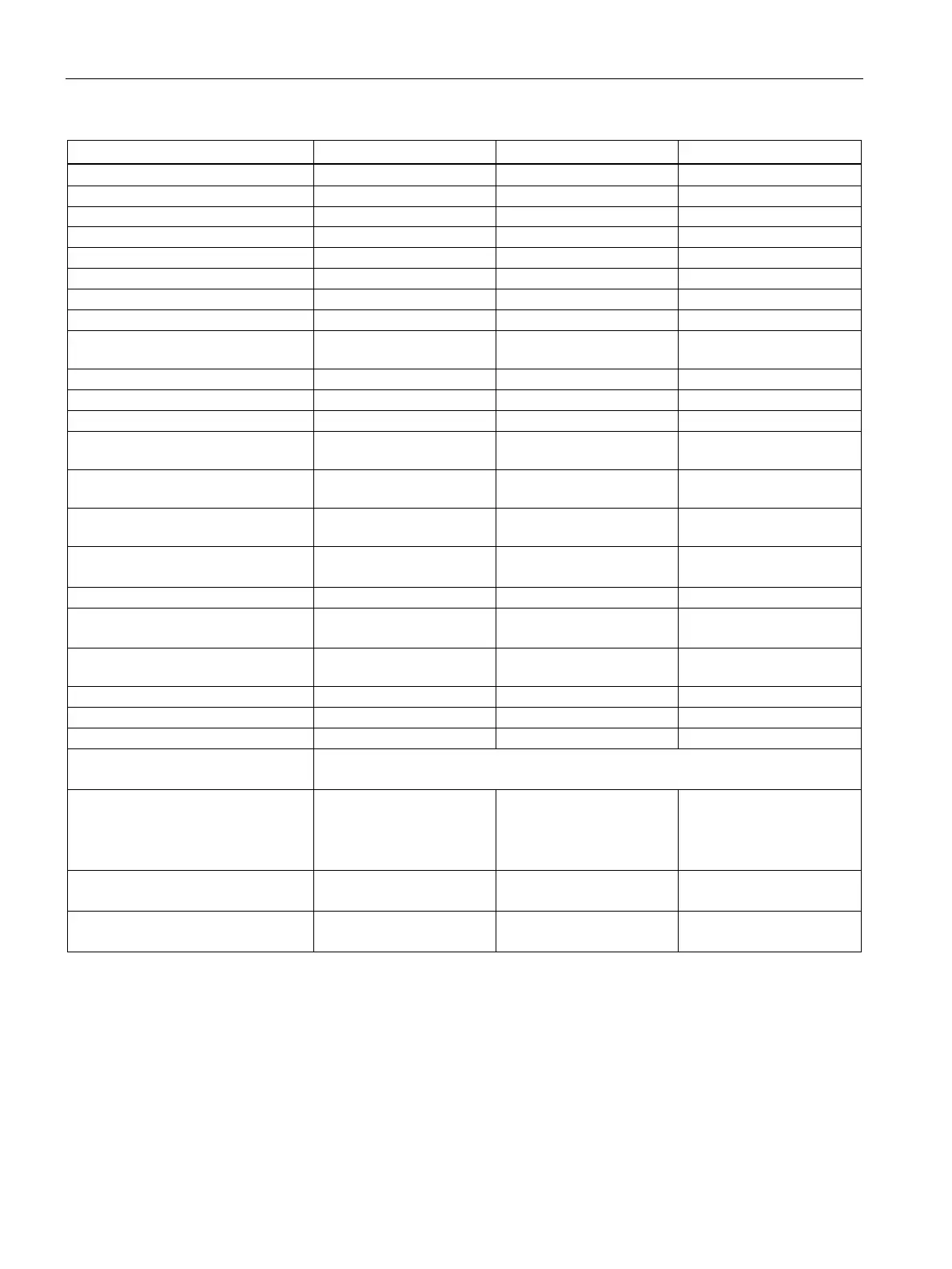
8.12 dv/dt filter plus VPL
Power Module PM240-2
162 Hardware Installation Manual, 01/2020, A5E33294624B AL
Article number JTA: TEF1203
Rated voltage (phase to phase)
Rated output current (rms)
Maximum output current (rms)
Inductance (Tolerance ± 5%)
Output current maximum pulse fre-
quency
Maximum voltage rise at motor ter-
minals
1)
Maximum peak voltage at motor
terminals (phase to phase)
2) 3)
Maximum peak voltage at motor
terminals (phase to earth)
2)
Maximum cable length filter - motor
(screened / unscreened)
3)
450 m / 650 m
525 m / 800 m
450 m / 650 m
525 m / 800 m
450 m / 650 m
525 m / 800 m
Rated terminal cross section (load
circuit)
Rated terminal cross section (DC
link feedback)
4)
Metrical (mm² / Nm)
Imperial (AWG / lbf.in)
3/0 / 115
4/0 / 115
2 x 4/0 / 115
185 / 13.0
Voltage rise according IEC/TS 60034-17
Under nominal DC link voltage
Maximum peak voltage at motor terminals < 1350V at cable length up to 450m screened or 650m unscreened Maximum
peak voltage at motor terminals < 1500V at cable length up to 525m screened or 800m unscreened
Short-circuit-proof wiring is required
Installing the filter in an enclosure is required
Higher ambient temperatures up to 60°C allowed with current derating at 40°C, in the range 40…50°C with 1.5% per 1K
and in the range 50…60°C with 1.9% per 1K

 Loading...


