2
10.04 Operation
2.13 Tools and tool offsets
2
Siemens AG, 2004. All rights reserved
SINUMERIK 840D/840Di/810D Operation/Programming ShopMill (BAS) – 10.04 Edition 2-149
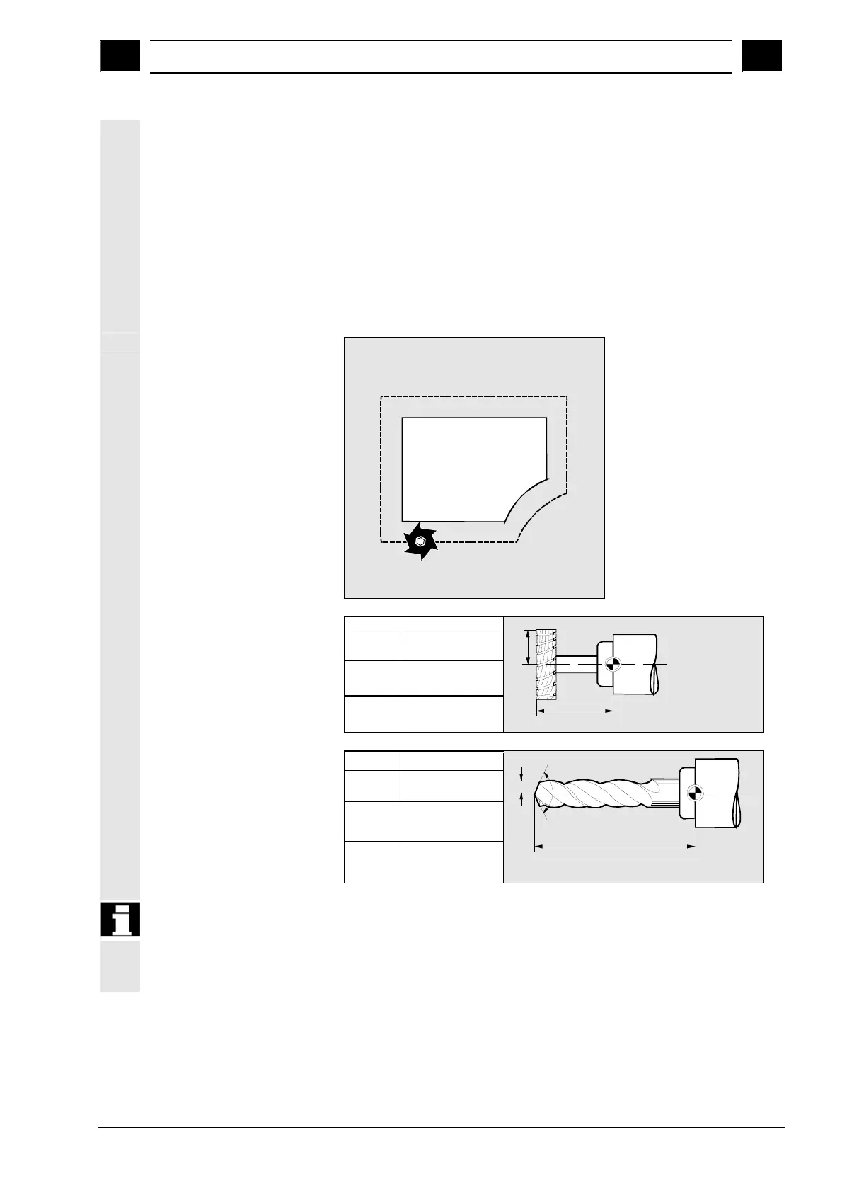
Tool radius
compensation
The contour and tool path are not identical. The cutter or tool nose
radius center must travel along a path that is equidistant from the
contour.
For this purpose, the programmed tool center point path is
automatically displaced by the control – as a function of radius and
machining direction – in such a way that the tool edge travels exactly
along the programmed contour.
The tool radius must be entered in the tool list. The control fetches the
required radii during program execution and calculates the tool path
from these values.
Equidistant
Offset values
milling tool (example)
F
Z
Length in Z
Radius in X/Y
Y
Length in Y
Radius in Z/X
Length in X
Radius in Y/Z
X
F - Toolholder
reference point
Radius
Length
Infeed
Geometry in plane
Offset values
drill (example)
Z
Length in Z
Y
Length in Y
Length in X
X
F - Toolholder reference point
Infeed
Geometry in plane
F
Length
F
Angle
Radius
Offset values are used in the simulation display and programming
graphic for the following tools:
• Drill: Angle and radius/diameter
• Centering tool: Radius/diameter