9
Examples 10.04
9.4 Exam
le 4: Slot side com
ensation
9
Siemens AG, 2004. All rights reserved
9-434 SINUMERIK 840D/840Di/810D Operation/Programming ShopMill (BAS) – 10.04 Edition
The work offset calculated from these is entered in the work offset list.
Program
1. Program header
• The blank dimensions correspond to the developed cylinder
peripheral surface.
X0 0 abs Y0 0 abs Z0 25 abs
X1 -130 abs Y1 157.08 abs Z1 22 abs
RP 50 SC 1
Note: Y1 is calculated according to equation: Y1 = ∅ • π
In this case: Diameter 50 multiplied by 3.14...
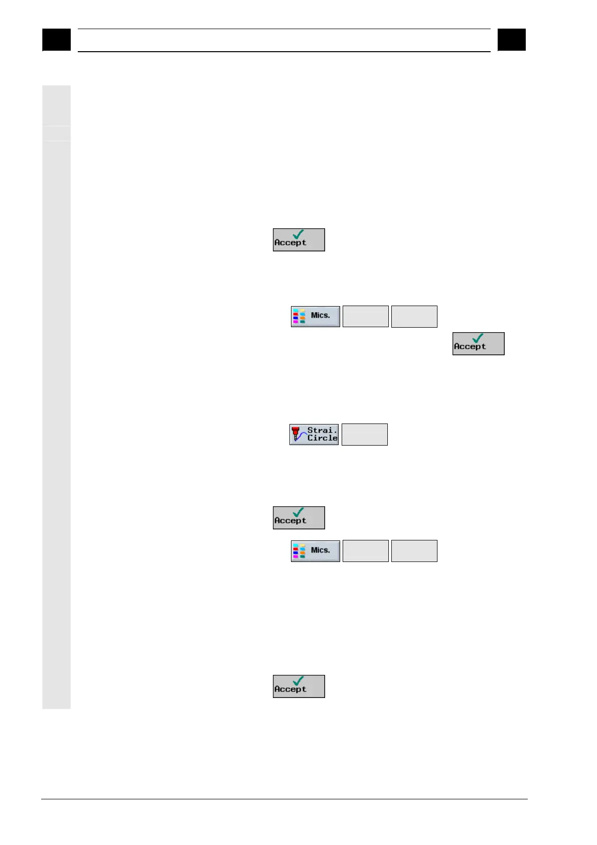
• Press the
softkey.
2. Activate the work offset
in the program
Select work offset for cylinder surface transformation (e.g. offset the
zero point on the center point of the cylinder end face).
• Select via the
Transfor-
mations>
Work
offset >
softkeys
• Select the required work offset and then press the
softkey.
3. Position the Y axis Position the tool in the Y axis over the center of the cylinder. The
reason for this is that the Y axis is not traversed after cylinder surface
transformation is selected.
• Select via the
Straight
line
softkeys
• Enter parameters:
X 10 abs Y 0 abs Z 40 abs
F *rapid traverse* mm/min Radius compensation off
• Press the
softkey.
4. Activate cylinder surface
transformation
• Select via the
Transfor-
mations>
Cylinder
surface >
softkeys
• Enter parameters:
Transformation On
∅ 50
Slot wall offset On
D 6
Note: D is the distance from the imaginary center-point path to the
slot wall.
• Press the
softkey.

 Loading...


