6 Assi
nin
Parameters to the Control and the PLC Pro
ram
6
03.96
6.9 Axes and spindles
6-135
Siemens AG 2000 All Rights Reserved
SINUMERIK 840D Installation and Start-Up Guide (IAD) – 04.00 Edition
MD 36100: POS_LIMIT_MINUS (1st software limit switch minus)
MD 36110: POS_LIMIT_PLUS (1st software limit switch plus)
MD 36120: POS_LIMIT_MINUS2 (2nd software limit switch minus)
MD 36130: POS_LIMIT_PLUS2 (2nd software limit switch plus)
IS “2nd software limit switch minus” (DB31, ... DBX12.2)
IS “2nd software limit switch plus” (DB31, ... DBX12.3)
Alarm “10620 channel [name1] block [no.] axis [name2] reaches software limit
switch +/–”
Alarm “10621 channel [name1] axis [name2] stationary at software limit switch
+/– (JOG)”
Alarm “10720 channel [name1] block [no.] axis [name2] programmed end point
is behind software limit switch +/–”
Working area limitations can be specified and activated for geometry axes via
setting data or from the part program (with G25/G26). Monitoring is active after
reference point approach.
SD 43400: WORKAREA_PLUS_ENABLE (working area limitation active in pos.
direction)
SD 43410: WORKAREA_MINUS_ENABLE (working area limitation active in
neg. direction)
SD 43420: WORKAREA_LIMIT_PLUS (working area limitation plus)
SD 43430: WORKAREA_LIMIT_MINUS (working area limitation minus)
Alarm “10630 channel [name1] block [no.] axis [name2] reaches working area
limitation +/–”
Alarm “10631 channel [name1] axis [name2] stationary at working area
limitation +/– (JOG)”
Alarm “10730 channel [name1] block [no.] axis [name2] programmed end point
is behind working area limitation +/–”
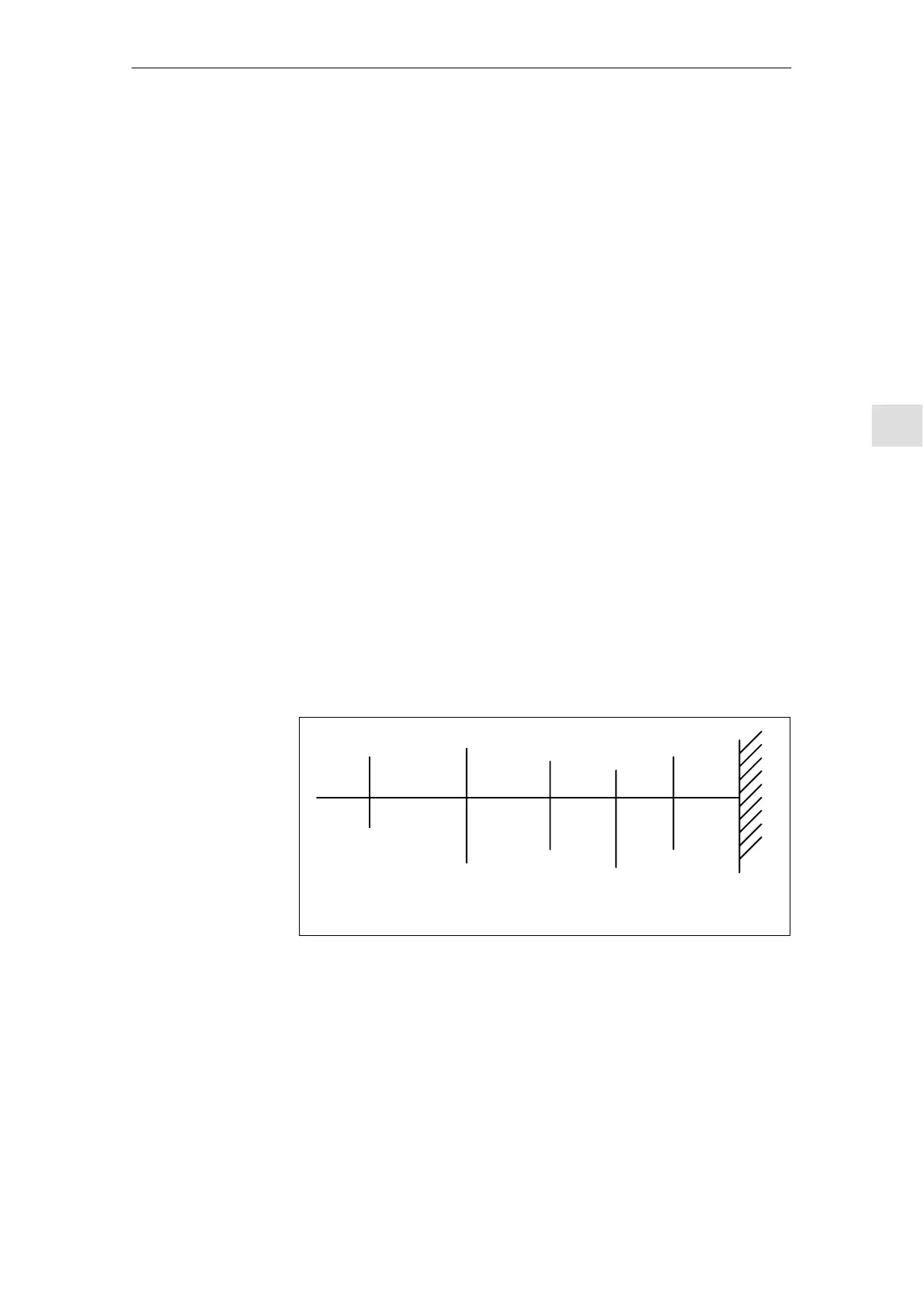
2nd software
limit switch
(activated via PLC)
1st software
limit switch
Hardware limit
switch
Mechanical
traversing
limit
EMERGENCY STOP
Working
area limita-
tion
(for geome-
try axes
only)
Fig. 6-20 Overview of travel limits
Machine data,
interface signals
and alarms
Monitoring of
positions via
working area
limitations
Setting data and
alarms

 Loading...


