Pin assignment
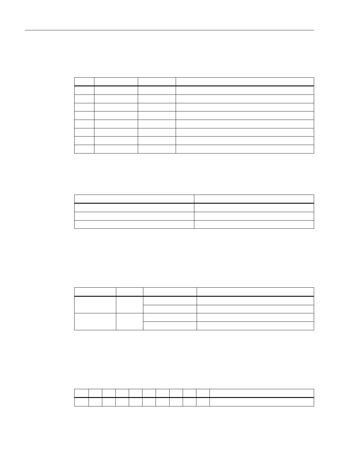
Table 12-17 PROFINET interfaces X2, ports 1, 2
Pin Signal name Signal type Meaning
1 TX+ O Transmit data +
2 TX- O Transmit data -
3 RX+ I Receive data +
4 N.C. - Reserved, do not use
5 N.C. - Reserved, do not use
6 RX- I Receive data -
7 N.C. - Reserved, do not use
8 N.C. - Reserved, do not use
Cable specication
Table 12-18 Cable specication at X2, ports 1, 2
Characteristic Version
Connector type RJ45 socket
Cable type Industrial Ethernet cable (as of CAT5)
Max. cable length 100 m
LED displays
For diagnostic purposes, the RJ45 sockets are each equipped with a green and a yellow LED. This
allows the following information to be displayed for the respective PROFINET port:
Table 12-19 PROFINET ports LED displays
Name Color Status Meaning
Link Green lit Transfer rate 100 Mbit/s
o No or faulty connection
Activity Orange lit Data exchange
o No data exchange
PROFINET address (S1)
A logical address can be assigned to the I/O module for communication with PROFINET using a
10-bit DIP switch S1.
Table 12-20 General settings with switch S1
1 2 3 4 5 6 7 8 9 10 Meaning
on on PROFINET functionality
Connectable components
12.2PP 72/48D PN and PP 72/48D 2/2A PN
NCU 1750
124 Equipment Manual, 10/2023, A5E45627807B AH
 Loading...


