2 Functions
106
7UT613/63x Manual
C53000-G1176-C160-2
I
stab
= |I
1
| + |I
2
|
The current sum definition is extended for more than 2 measurement locations, e.g.
for 4 measuring locations (figure 2-18 or 2-19), therefore:
I
diff
= |I
1
+ I
2
+I
3
+ I
4
|
I
stab
= |I
1
| + |I
2
| + |I
3
| + |I
4
|
I
diff
is derived from the fundamental frequency current and produces the tripping effect
quantity, I
stab
counteracts this effect.
To clarify the situation, three important operating conditions with ideal and matched
measurement quantities are considered.
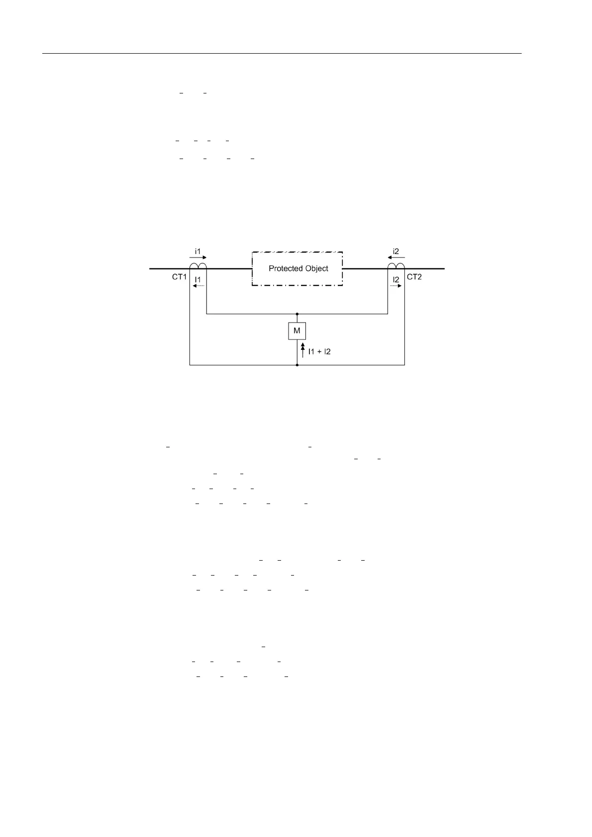
Figure 2-20 Definition of current direction
1. Through-flowing current under undisturbed conditions or external fault:
I
1
flows into the protected zone, I
2
leaves the protected zone, i.e. is negative ac-
cording tot he definition of signs, therefore I
2
= –I
1
;
moreover |I
2
|=|I
1
|
I
diff
=|I
1
+ I
2
|=|I
1
– I
1
|=0
I
stab
=|I
1
|+|I
2
|=|I
1
|+|I
1
|=2·|I
1
|
No tripping effect (I
diff
= 0); the stabilisation (I
stab
) corresponds to double the
through-flowing current.
2. Internal short-circuit, e.g. fed with equal currents each side:
The following appliesI
2
= I
1
; moreover |I
2
|=|I
1
|
I
diff
=|I
1
+ I
2
|=|I
1
+ I
1
|=2·|I
1
|
I
stab
=|I
1
|+|I
2
|=|I
1
|+|I
1
|=2·|I
1
|
Tripping effect (I
diff
) and restraint value (I
stab
) are equal and correspond to the total
fault.
3. Internal short-circuit, fed from one side only:
The following applies I
2
= 0
I
diff
=|I
1
+ I
2
|= |I
1
+0|=|I
1
|
I
stab
=|I
1
|+|I
2
|=|I
1
|+0=|I
1
|
Tripping quantity (I
diff
) and stabilising quantity (I
stab
) are equal and correspond to
the single-sided fault current.
This result shows that for internal fault I
diff
= I
stab
. Thus, the characteristic of internal
faults is a straight line with the slope 1 (45°) in the operation diagram (dash-dotted fault
characteristic in figure 2-21).
 Loading...


