2.2 Differential Protection
105
7UT613/63x Manual
C53000-G1176-C160-2
All following considerations are based on the convention that all currents flowing into
the protected zone are defined as positive unless explicitly stated otherwise.
Basic Principle with
more than Two
Sides
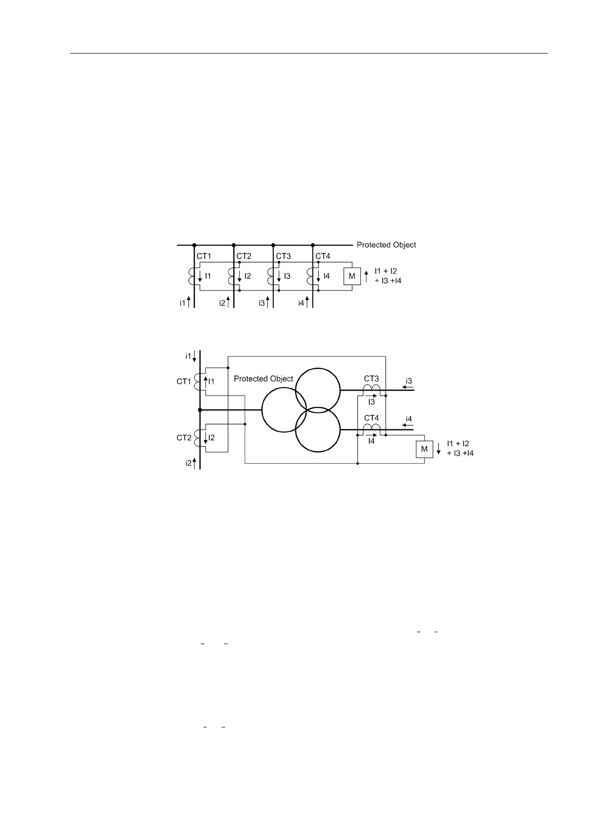
For protected objects with three or more sides or for busbars, the differential principle
is expanded in that the total of all currents flowing into the protected object is zero in
healthy operation, whereas in case of a fault the total in-flowing current is equal to the
fault current.
See figure 2-18 as an example for four feeders. The three-winding transformer in
figure 2-19 has 4 measuring locations, so it is treated by the differential protection like
a „4-winding“ transformer.
Figure 2-18 Basic principle of differential protection for four ends (single-phase illustration)
Figure 2-19 Basic principle of differential protection for 4 measuring locations — example of
a three-winding power transformer with 4 measuring locations (single-phase il-
lustration)
Current Restraint When an external fault causes a heavy current to flow through the protected zone, dif-
ferences in the magnetic characteristics of the current transformers CT1 and CT2
(figure 2-17) under conditions of saturation may cause a significant current flow
through the measuring element M. If it is greater than the respective pickup threshold,
the device can trip even though no fault occurred in the protected zone. Current re-
straint (stabilisation) prevents such erroneous operation.
In differential protection systems for protected objects with two terminals, a restraining
quantity is normally derived from the current difference |I
1
– I
2
| or from the arithmetical
sum |I
1
| + |I
2
|. Both methods are equal in the relevant ranges of the stabilisation char-
acteristics. For protected objects with more than two ends, such as multi-winding
transformers, busbars etc, only the arithmetical sum method is possible. The latter
method is used in 7UT613/63x for all protected objects. The following definitions apply
for 2 measuring points:
a tripping or differential current
I
diff
= |I
1
+ I
2
|
and the stabilisation or restraining current
 Loading...


