2 Functions
114
7UT613/63x Manual
C53000-G1176-C160-2
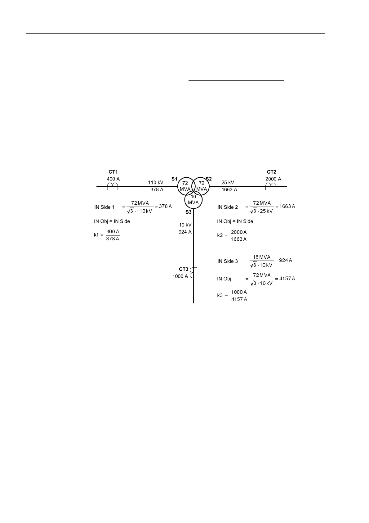
Concerning power transformers with more than two windings, the windings may have
different power ratings. In order to achieve comparable currents for the differential pro-
tection, all currents are referred to the winding (= side) with the highest power rating.
This apparent power is named the rated power of the protected object
.
Figure 2-27 shows an example of a three-winding power transformer. Winding 1 (S1)
and 2 (S2) are rated for 72 MVA; The settings recommended are the same as in figure
2-26. But the third winding (S3) has 16 MVA rating (e.g. for auxiliary supply). The rated
current of this winding (= side of the protected object) results in 924 A. On the other
hand, the differential protection has to process comparable currents. Therefore, the
currents of this winding must be referred to the rated power of the protected object, i.e.
72 MVA. This results in a rated current (i.e. the current under nominal conditions of the
protected object, 72 MVA) of 4157 A. This is the base value for the third winding:
These currents must be multiplied by the factor k3.
Figure 2-27 Magnitude matching — example of a three-winding power transformer (phase
relation not considered)
The device carries out this magnitude matching internally, based on the nominal
values set according to Subsection „General Power System Data“ under margin
heading „Object Data with Transformers“, and „Current Transformer Data for 3-phase
Measuring Locations“). Once the vector group has been entered, the protective device
is capable of performing the current comparison according to fixed formulae.
Conversion of the currents is performed by programmed coefficient matrices which
simulate the difference currents in the transformer windings. All conceivable vector
groups (including phase exchange) are possible. In this regard, the conditioning of the
starpoint(s) of the power transformer is also essential.
 Loading...


