3.1 Mounting and Connections
357
7UT613/63x Manual
C53000-G1176-C160-2
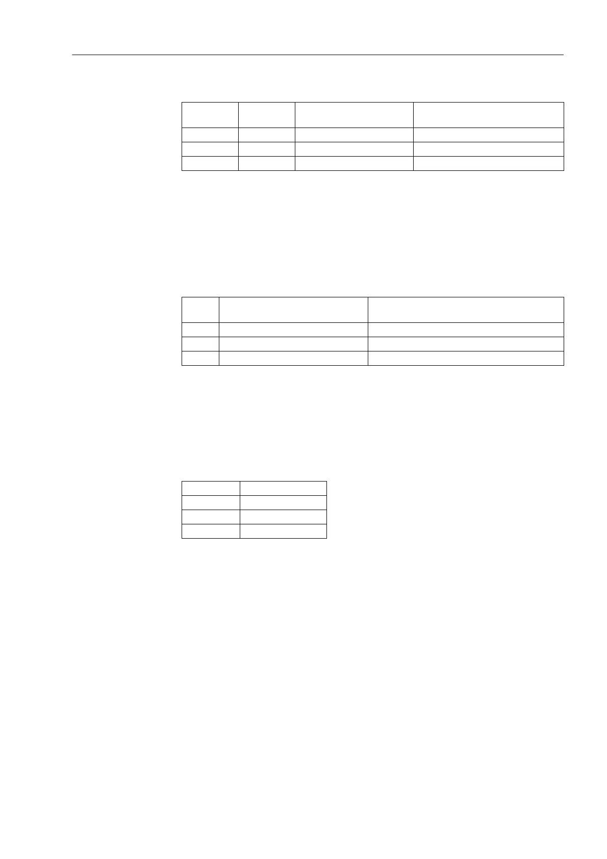
Table 3-11 Jumper setting for the contact type of the relay for BO6 to BO8
1)
Delivery state
The relay contacts for binary outputs BO1 through BO5 can be connected to common
potential, or configured individually for BO1, BO4 and BO5 (BO2 and BO3 are without
function in this context) (see also General Diagrams in the Appendix A.2).
Table 3-12 Jumper settings for the configuration of the common potential of BO1 through
BO5 or for configuration of BO1, BO4 and BO5 as single relays
1)
Delivery state
Jumpers X71 through X73 on the input/output board C-I/O-2 serve for setting the bus
address. Their position may not be changed. The following table shows the preset
jumper positions.
Table 3-13 Jumper Position of the Module Addresses of the input/output board C-I/O-2
The rated currents of the measured current inputs can be determined for each ana-
logue input via jumpers. With default settings all jumpers are set to the same rated
current (according to the order number of the device).
for Jumper Quiescent state open
(close)
1)
Quiescent state closed
(open)
BO6 X41 1-2 2-3
BO7 X42 1-2 2-3
BO8 X43 1-2 2-3
Jumper BO1 to BO5
connected to common potential
1)
BO1, BO4, BO5 configured as single relays
(BO2 and BO3 without function)
X80 1-2, 3-4 2-3, 4-5
X81 1-2, 3-4 2-3, 4-5
X82 2-3 1-2
Jumper Presetting
X71 1-2 (H)
X72 1-2 (H)
X73 2-3 (L)
 Loading...


