3.3 Commissioning
401
7UT613/63x Manual
C53000-G1176-C160-2
• Phase angle measurement for measuring location M1 with test current:
Check the phase angle under measurement values → secondary → phase
angles of side 1 of the protected object. All angles are referred to I
L1M1
. The follow-
ing values must result approximately for a clockwise phase rotation:
ϕ
L1 M1
≈ 0°
ϕ
L2 M1
≈ 240°
ϕ
L3 M1
≈ 120°
If the angles are wrong, reverse polarity or swapped phase connections on measur-
ing location M1 may be the cause.
– Switch off the test source and the protected object (shut down the generator) and
earth it.
– Re-check the plant connections to the device and the test arrangement and
correct them.
– Repeat test and re-check the current angles.
• Phase angle measurement for measuring location M2 with test current:
Check the phase angle under measurement values → secondary → phase
angles of measuring location M2 of the protected object. All angles are referred to
I
L1M1
.
Consider that always the currents flowing into the protected object are defined as
positive: That means that, with through-flowing in-phase currents, the currents
leaving the protected object at measuring location M2, have reversed polarity (180°
phase displacement) against the corresponding in-flowing currents at measuring lo-
cation M1.
Exception
: With transverse differential protection, the currents of the corresponding
phase have equal phase!
For clockwise phase rotation and without phase displacement, the angles should
be approximately:
ϕ
L1 M2
≈ 180°
ϕ
L2 M2
≈ 60°
ϕ
L3 M2
≈ 300°
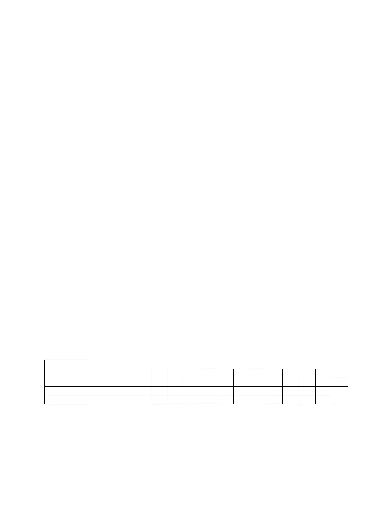
When measuring across a power transformer, approximately the values according
to Table 3-28 result for clockwise phase rotation:
Table 3-28 Displayed phase angle dependent on the protected object (three-phase)
1)
Angles are valid if the high voltage side is defined as side 1, otherwise read 360° minus the
stated angle
Protected Object Generator/Motor/
Busbar/Line
Transformer with Vector Group Numeral
1)
Phase Angle ↓ 01234567891011
ϕ
L1M2
180° 180° 150° 120° 90° 60° 30° 0° 330° 300° 270° 240° 210°
ϕ
L2M2
60° 60° 30° 0° 330° 300° 270° 240° 210° 180° 150° 120° 90°
ϕ
L3M2
300° 300° 270° 240° 210° 180° 150° 120° 90° 60° 30° 0° 330°
 Loading...


