System overview
1.10 Connection to the higher-level control
SIRIUS Innovations
88 System Manual, 01/2011, A8E56203870002-03
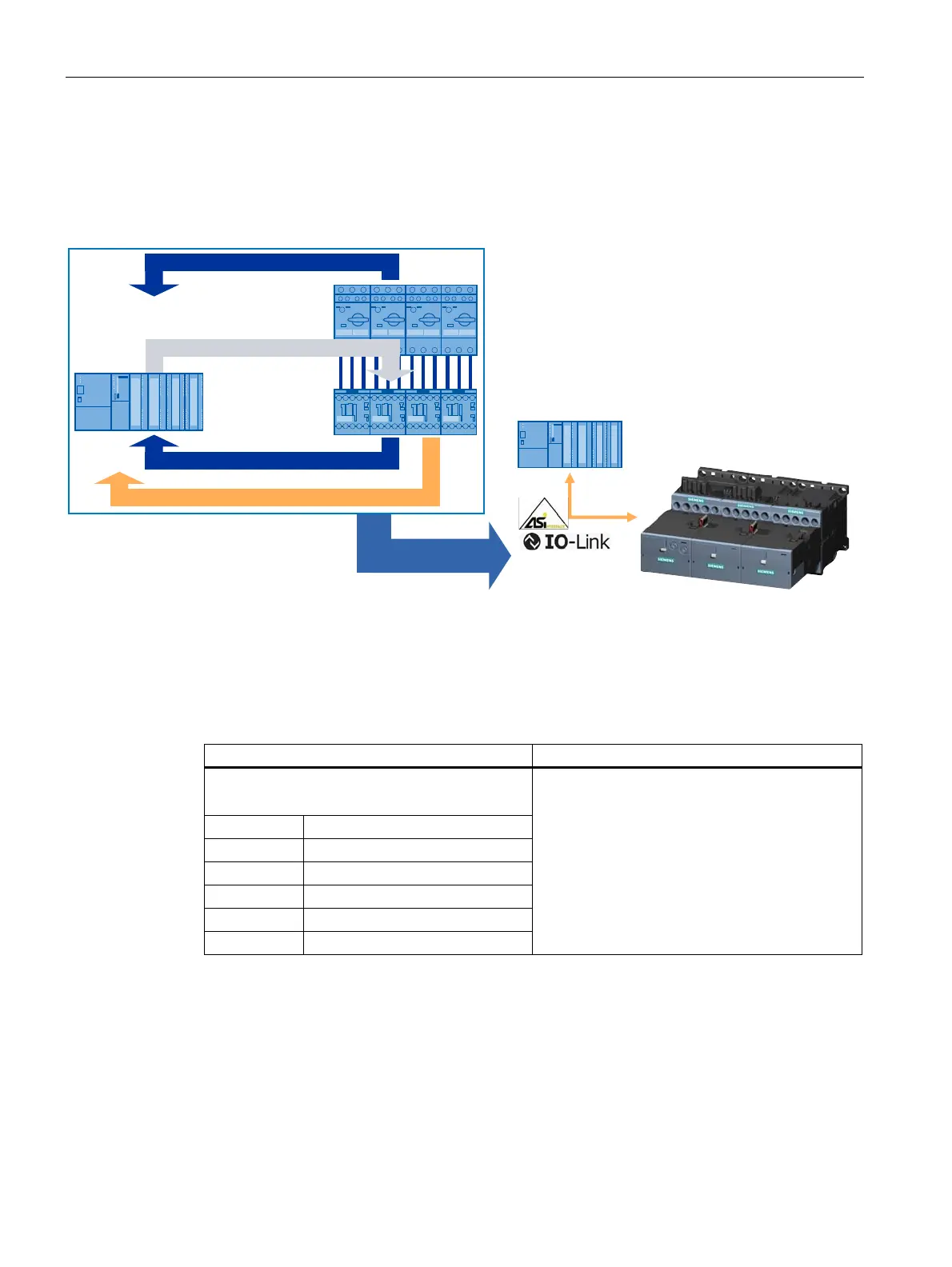
SIRIUS switching devices are connected to the automation level via AS-Interface or IO-Link,
without any additional wiring. These interfaces ensure that information about the switch
position and the readiness of the feeder for operation is transferred, and that contactor
control is implemented. In addition to these three items of information relating to feeders, IO-
Link also transfers diagnostics data.
SPS
SPS
5HDG\
'LDJQRVWLFV
$FWXDWLRQ
)HHGEDFNRI
VZLWFKLQJVWDWXV
Figure 1-40 Communication via AS-Interface or IO-Link
SIRIUS 3RA27 function modules or SIRIUS 3RA6 compact starters can communicate with a
higher-level control either via the AS-i fieldbus or via the IO-Link wiring system. Cyclic data
transmission (DIs and DOs) is identical for both IO-Link and AS-i.
Table 1- 36 Motor starter profile
Standard motor starter profile Group diagnostics (only with IO-Link)
4 DI, 2 DO (per feeder)
2 LEDs for "Device" and "Group fault"
DI 0.0 Ready
DI 0.1 Motor ON
DI 0.2 Group fault
DI 0.3 Group warning
DO 0.0 Motor ON or Motor CW
DO 0.1 Motor CCW
Device fault
No main voltage (motor starter protector
tripped)
Auxiliary voltage 24 V DC (U
aux
) missing
Signaling limit position right/left
Manual/local mode
 Loading...


