System overview
1.10 Connection to the higher-level control
SIRIUS Innovations
System Manual, 01/2011, A8E56203870002-03
93
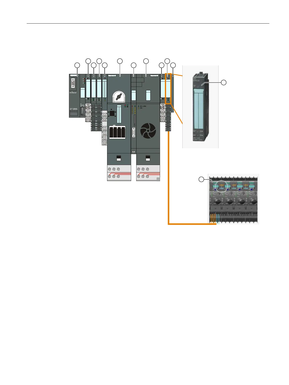
The figure below uses an example to show where the SIRIUS 4SI electronic module is
positioned within the SIRIUS controls.
IM 151-1
STANDARD
6ES7 151-
1AA05-0AB0
PM-E
DC24V
6ES7 138-
4CA01-0AA0
P15S23-A0
6ES7 193-
4CD20-0AA0
4DI
DC24V
6ES7 131-
4BD01-0AA0
E15S26-A1
6ES7 193-
4CA40-0AA0
4DI
DC24V
6ES7 131-
4BD01-0AA0
E15S26-A1
6ES7 193-
4CA40-0AA0
PWR
CON
SF
PM-D
DC24V
3
1
1
1
2
1
P15S27-01
3RK1 903-
0AA00
DS1e-x
3RK1 301-0AB10-0AA4
2 T1 4 T2 6 T3
1 L1 3 L2 5 L3
DS65-S32
3RK1 903-
0AK00
ICU24
6SL3 244-
0SA00-1AA1
ICU15
3RK1 903-
3EA10
2U 4V 6W
1L1 3L2 5L3
PM-E
DC24V
6ES7 138-
4CA01-0AA0
P15S23-A0
6ES7 193-
4CD20-0AA0
4 IO-Link
DC24V
6ES7 138-
4GA50-0AB0
E15S26-A1
6ES7 193-
4CA40-0AA0
1 Interface module IM...
2 Power module electronic PM-E
3 Electronic module, e.g. SIRIUS 4SI, DI, DO, AI, AO, CP, FM
4 Power module drives PM-D
5 Motor starter
6 Frequency converter ICU
7 Frequency converter IPM
8 Termination module
9 SIRIUS modular system with IO-Link (e.g. SIRIUS 3RA6 compact starters)
Figure 1-42 Options for connection to the automation level
 Loading...


