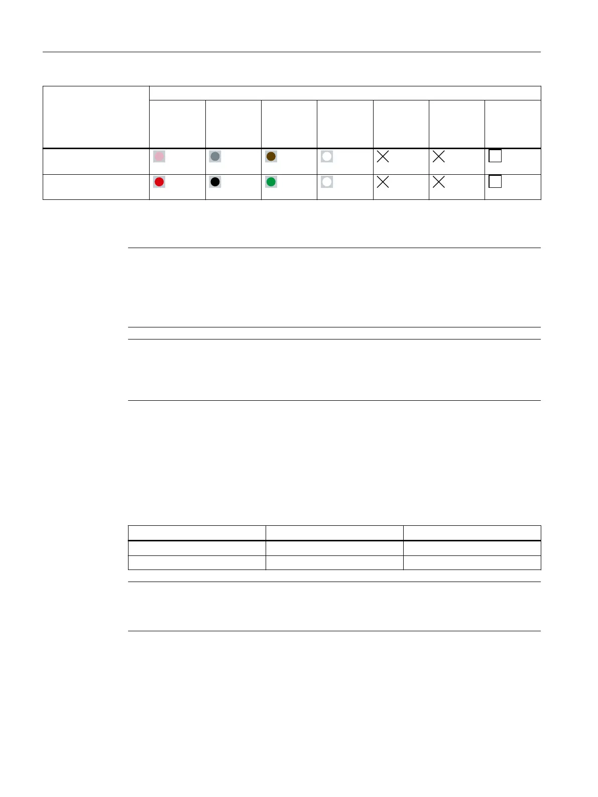
Load cell Function/color of connecting cable
EXC+ EXC- SIG+ SIG- Sense+ Sense- Shield not
connected
to the load
cell body
SIWAREX WL280
RN-S SA
Pink Gray Brown White n.a. n.a. Trans‐
parent
SIWAREX WL290
DB-S CA
Red Black Green White n.a. n.a. Trans‐
parent
Procedure
Note
Measurement errors
Observe the warnings concerning extending or shortening the connecting cables in section
→ Lengthening and shortening the connecting cable (Page 35).
If at all possible, do not shorten the connecting cables in a four-wire system.
Note
No calibration approval
In scales requiring ocial calibration, the connecting cables for load cells in a four-wire system
must not be shortened or lengthened.
1. Connect the recommended grounding cables: → Planning (Page 31)
2. Connect the load cells in accordance with the connection principle and with reference to the
specied signal assignments: → Connecting principle (Page 26)
3. For load cells with a four-wire system, position the wire jumpers in the junction box as
follows:
Table 5-2 Wire jumpers for load cells with four-wire system
Wire jumper From terminal To terminal
1 EXC- SENSE-
2 EXC+ SENSE+
Note
Malfunction
If the wire jumpers are missing, the SIWAREX weighing module signals a wire break.
Connecting
5.3 Connecting up
SIWAREX WL200
30 Operating Instructions, 12/2021, A5E02199611B-13

 Loading...