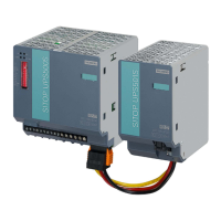
Analyzers envisaged for use in hazardous areas must be provided with a safety bracket which
protects the power connector from being unintentionally disconnected (see upper arrow in
image above). This bracket is enclosed loose with the analyzer and must be attached before
switching on.
4.2.2 Connection of the signal lines
NOTICE
Incorrect power supply
The 24 V/1 A power supply must be a power-limited safety extra-low voltage with safe electrical
isolation (SELV).
Only connect the signal lines to devices which also have reliable electric isolation from their
power supply.
• The connection lines to the relay outputs, binary inputs, and analog outputs must be
shielded.
• The analog outputs are oating, but have a common negative pole.
• As a measure to suppress sparking across the relay contacts (e.g. limit relays), RC elements
must be connected as shown in the following gure. Note that the RC element results in a
drop-out delay for an inductive component (e.g. solenoid valve). The RC element should be
sized according to the following rule of thumb:
– R=R
L
/2; C=4L/R
2
L
,
where R=100Ω and C=200nF are sucient.
– You must use a non-polarized capacitor for the RC element.
6ROHQRLGYDOYH
'HYLFHVLGH
&RQQHFWLRQVLGH
24 V
R
C
Figure4-1 Measure to suppress sparks on a relay contact
When operated with direct current, a spark suppression diode can be installed instead of the
RC element.
Connecting
4.2Electrical connection
Series 6 and ULTRAMAT 23
Compact Operating Instructions, 01/2024, A5E45779144002-AB 33
 Loading...