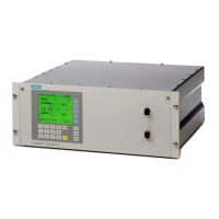
4.4.2 Connection diagrams for CALOMAT 6E
6DPSOHJDVRXWOHW
6DPSOHJDVLQOHW
3XUJLQJJDVLQOHW
RU
When installing in a cabinet, mount analyzer on support rails or telescopic rails
① 9-pin connector RS485
② 15-pin connector, relay outputs and binary inputs
③ 25-pin connector, analog inputs and outputs
④ 9-pin interface connector for PROFIBUS (option)
⑤ 37-pin connector, relay outputs and binary inputs (option)
⑥ Power connection and ne fuses
⑦ Potential connection
Figure4-10 CALOMAT 6E, gas connections and electrical connections
See also
Gas connections (Page39)
Connecting
4.4Connection diagrams
Series 6 and ULTRAMAT 23
42 Compact Operating Instructions, 01/2024, A5E45779144002-AB

 Loading...


