05.2006 First Start-up
Siemens AG 6SE7087-2JD60
SIMOVERT MASTERDRIVES Operating Instructions 3-1
3 First Start-up
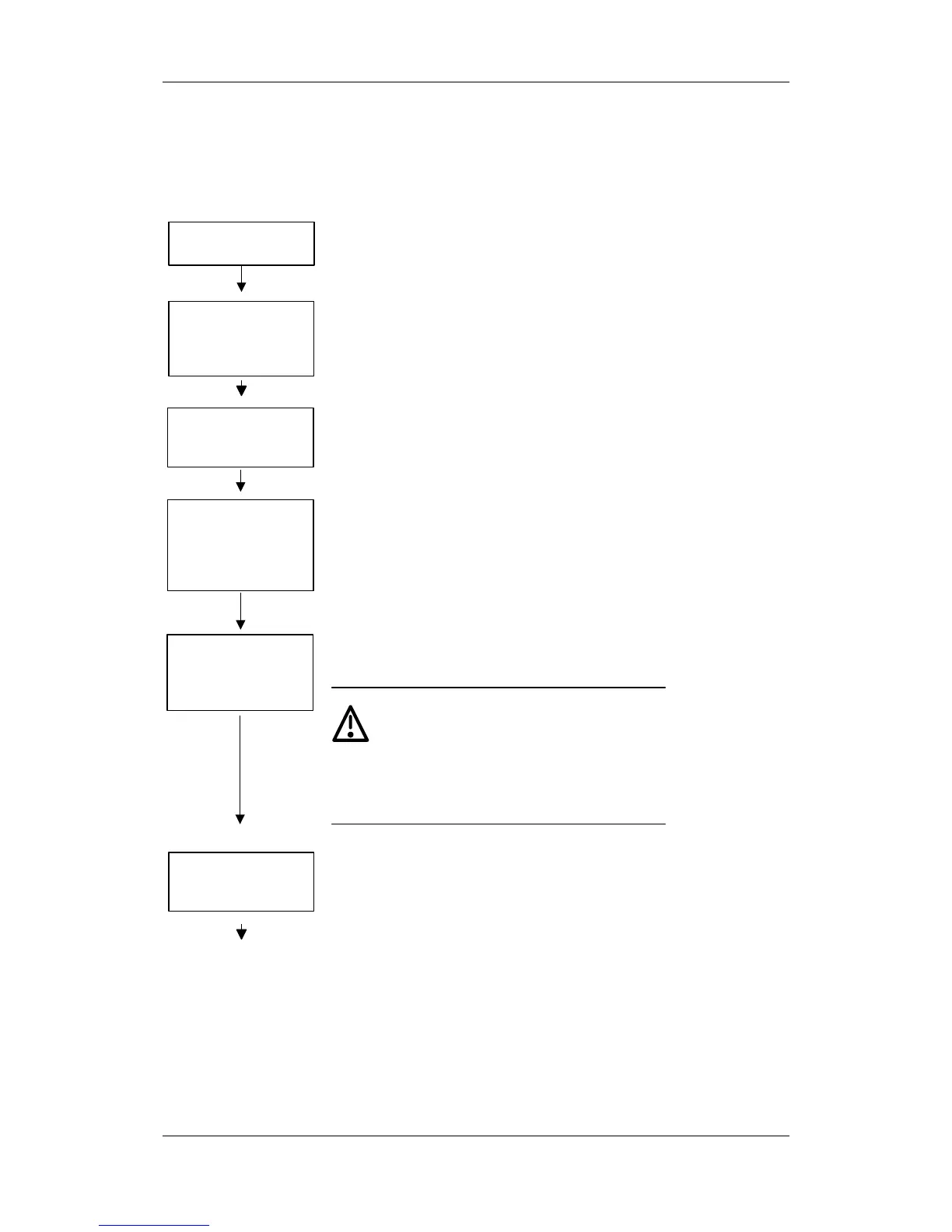
After removing the packaging, check that the unit is
intact and undamaged. Only intact units may be started
up. Also check the unit to ensure it is complete and that
the optional boards are correctly equipped on the basis
of the package label (on the outside of the packaging).
Unpack and check the
units
See section
"Transport,
Storage,
Unpacking"
Retrofit any optional boards which have not yet been
installed, if necessary. Then install the units taking into
account the requirements at the point of installation and
the EMC instructions.
Mount the unit and
install optional boards
which have not yet
been fitted
See section
"Installation"
and "Installation
in Conformance
with EMC
Regulations"
If the DC link of the unit was de-energized for more than
one year, you have to newly form the DC link capacitors
Form the DC link
capacitors,
if necessary
See section
"Forming"
Beginning with the PE conductor connect the power
cables or the DC link busbars and the 230 V~ for the fan.
If configured, also connect the external 24 V incoming
power supply. Pay attention to EMC instructions when
laying the cables. Please do not at this stage connect
any control, communication, encoder and motor cables
(exception: cable for connecting up an OP1S, if
parameterization is to be effected via the OP1S).
Connect the protective
conductor, the power
cables or buses and, if
present, the ext. 24 V
supply
See section
"Connecting-up"
and
"Installation in
Conformance
with EMC
Regulations"
Please connect the remaining control, communication,
encoder and motor cables. Pay attention to the EMC
instructions when laying the cables.
Connect the control
cables, communication
cables, encoder cables
and motor cables
See section
"Connecting-up"
and "Installation
in Conformance
with EMC
Regulations"
WARNING
The device must be
disconnected
from
its voltage supplies (24 V DC electronics
supply
and
DC link / mains voltage)
before the control and encoder leads are
connected or disconnected!
Failure to observe this advice can result in
encoder defects, which may in turn cause
uncontrolled axis movements.
After checking that the cabling has been correctly
connected and that it sits properly, power up the
external 24 V supply or the line voltage. After the
electronics power supply has been started, the unit
initializes itself. The action can take several seconds.
The drive status is subsequently shown on the PMU.
Power up the external
24 V supply or the line
voltage
111