Installation 05.2006
6SE7087-2JD60 Siemens AG
5-4 Operating Instructions SIMOVERT MASTERDRIVES
5.2 Installing the optional boards
The boards may only be replaced by qualified personnel.
It is not permitted to withdraw or insert the boards under voltage.
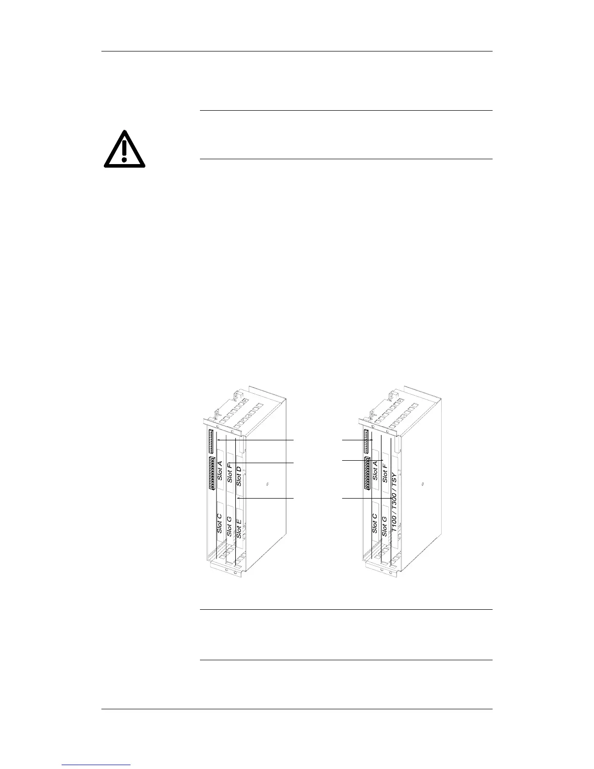
A maximum of six slots are available in the electronics box of the unit
for installing optional boards. The slots are designated with the letters A
to G. Slot B is not provided in the electronics box. It is used in units of
the Compact PLUS type of construction.
If you wish to use slots D to G, you will additionally require the
following:
♦ Bus expansion LBA (Local Bus Adapter), which is used for mounting
the CU board and up to two adaption boards, and
♦ An adaption board (ADB - Adaption Board) on which up to two
optional boards can be mounted.
The slots are situated at the following positions:
♦ Slot A CU board Position: top
♦ Slot C CU board Position: bottom
♦ Slot D Adaption board at mounting position 2 Position: top
♦ Slot E Adaption board at mounting position 2 Position: bottom
♦ Slot F Adaption board at mounting position 3 Position: top
♦ Slot G Adaption board at mounting position 3 Position: bottom
Mounting
position 1
Mounting
position 3
Mounting
position 2
Fig. 5-4 Position of the slots for Compact and chassis type units
Mounting position 2 can be used for technology boards (T100, T300,
TSY).
Mounting positions 2 and 3 can also be used for communication boards
SCB1 and SCB2.
WARNING
Slots
NOTE