05.2006 Faults and Alarms
Siemens AG 6SE7087-2JD60
SIMOVERT MASTERDRIVES Operating Instructions 14-1
14 Faults and Alarms
14.1 Faults
General information regarding faults
For each fault, the following information is available:
Parameter r947 Fault number
r949 Fault value
r951 Fault list
P952 Number of faults
r782 Fault time
If a fault message is not reset before the electronic supply voltage is
switched off, then the fault message will be present again when the
electronic supply is switched on again. The unit cannot be operated
without resetting the fault message. (Exception: Automatic restart has
been selected, see P373).
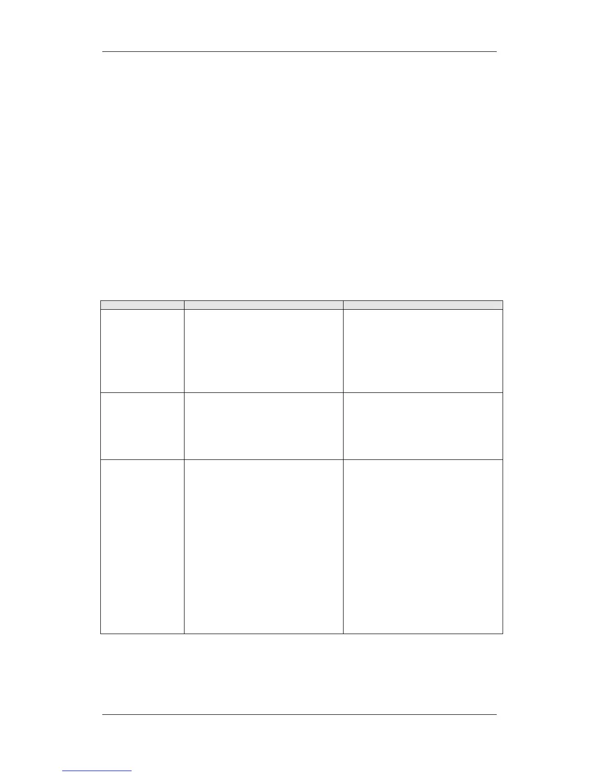
Number / Fault Cause Counter-measure
F001
Main contactor
checkback
If a main contactor checkback is configured,
no checkback occurs within the time set in
P600 after the power-up command. In the
case of externally excited synchronous motors
(P095 = 12), there is no checkback for the
excitation current unit.
P591 Src Contactor Msg
Parameter value must be in conformance with
the connection of the main contactor
checkback.
Check the checkback loop of the main
contactor (or the checkback of the excitation
current unit in the case of synchronous
motors).
F002
Pre-charging
When pre-charging, the minimum DC link
voltage (P071 Line Volts x 1.34) of 80 % has
not been reached.
The maximum pre-charging time of 3 seconds
has been exceeded.
Check the supply voltage,
Compare witth P071 Line Volts (Compare
P071 with the DC link voltage on DC units).
Check the rectifier/regenerative unit on DC
units. The rectifier/regenerative unit must be
switched on before the inverter is switched on.
F006
DC link overvoltage
Shutdown has occurred due to excessive DC
link voltage.
Line voltage I DC voltage range I Shutdown
value
-------------------------------------------------------------
200 V - 230 V I 270 V - 310 V I appr. 410 V
380 V - 480 V I 510 V - 650 V I appr. 820 V
500 V - 600 V I 675 V - 810 V I appr. 1020 V
660 V - 690 V I 890 V - 930 V I appr. 1220 V
For parallel-connected converters (BF M,N)
r949 = 1: Overvoltage in the DC link of the
master
r949 = 2: Overvoltage in the DC link of the
slave.
Check the supply voltage or input DC voltage.
Converter is operating in regenerative mode
without feedback possibility.
If the converter supply voltage is at the upper
tolerance limit and it is operating at full load,
F006 can also be caused by a line phase
failure.
Possibly
- Increaase P464 Decel Time,
- Activate P515 DC Bus Volts Reg (check
P071 beforehand)
- Reduce P526 Fly Search Speed.
- Reduce P259 Max Regen Power (only for
P100 = 3, 4 or 5)