05.2006 Connecting-up
Siemens AG 6SE7087-2JD60
SIMOVERT MASTERDRIVES Operating Instructions 7-3
-F101
-F102
U2 V2 W2 PE2
T1 T2 T3
Mount.pos. 1 (CUVC)
X101
PMU connection X108
Optional board
in slot C
Aux. contactor,
external DC24 V-
supply X9
Mains connection X1
Fan fuses
Mount. pos. 2
Mount. pos. 3
Adjustment of
fan voltage
Shield connections for control
cables and tachometer cables
Motor connection X2
Cable connection
adapter for EMC
(Option)
X103
Optional board
in slot A
DC link
connection X3
U1 V1 W 1 P E 1 CD
L1 L2 L3
L+
L-
X102
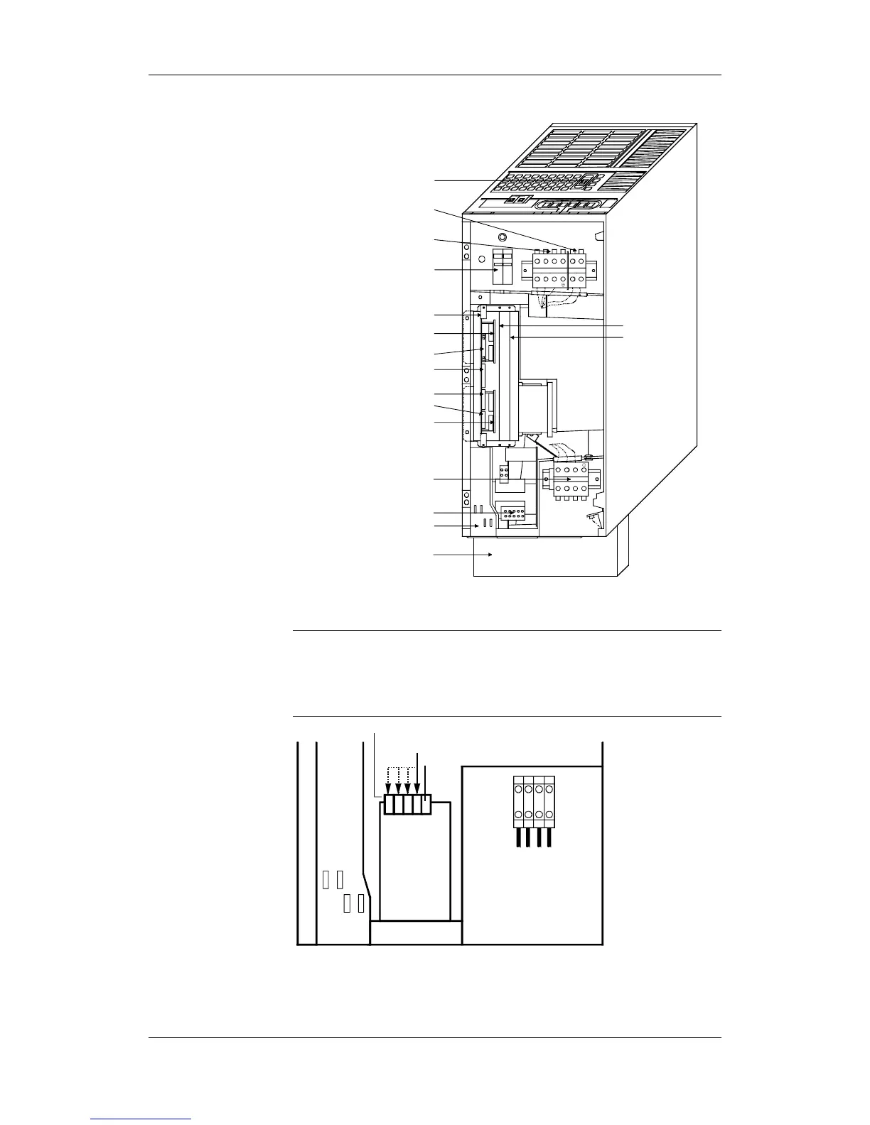
Fig. 7-2 Connection overview for type D
A 230 V fan is installed in drive converters, type of construction D. The
fan is supplied via the fan transformer. To supply the fan with 230 V,
the primary side of the fan transformer must be adjusted to the existing
line voltage via the plug connector (Connection 2). (For supply voltage
range, see terminal).
X2
Transformer terminals
Connection 2
0 V
Connection 1
Fan-
transformer
Fig. 7-3 Transformer location (only for converters, type of construction D)
NOTE