Connecting-up 05.2006
6SE7087-2JD60 Siemens AG
7-10 Operating Instructions SIMOVERT MASTERDRIVES
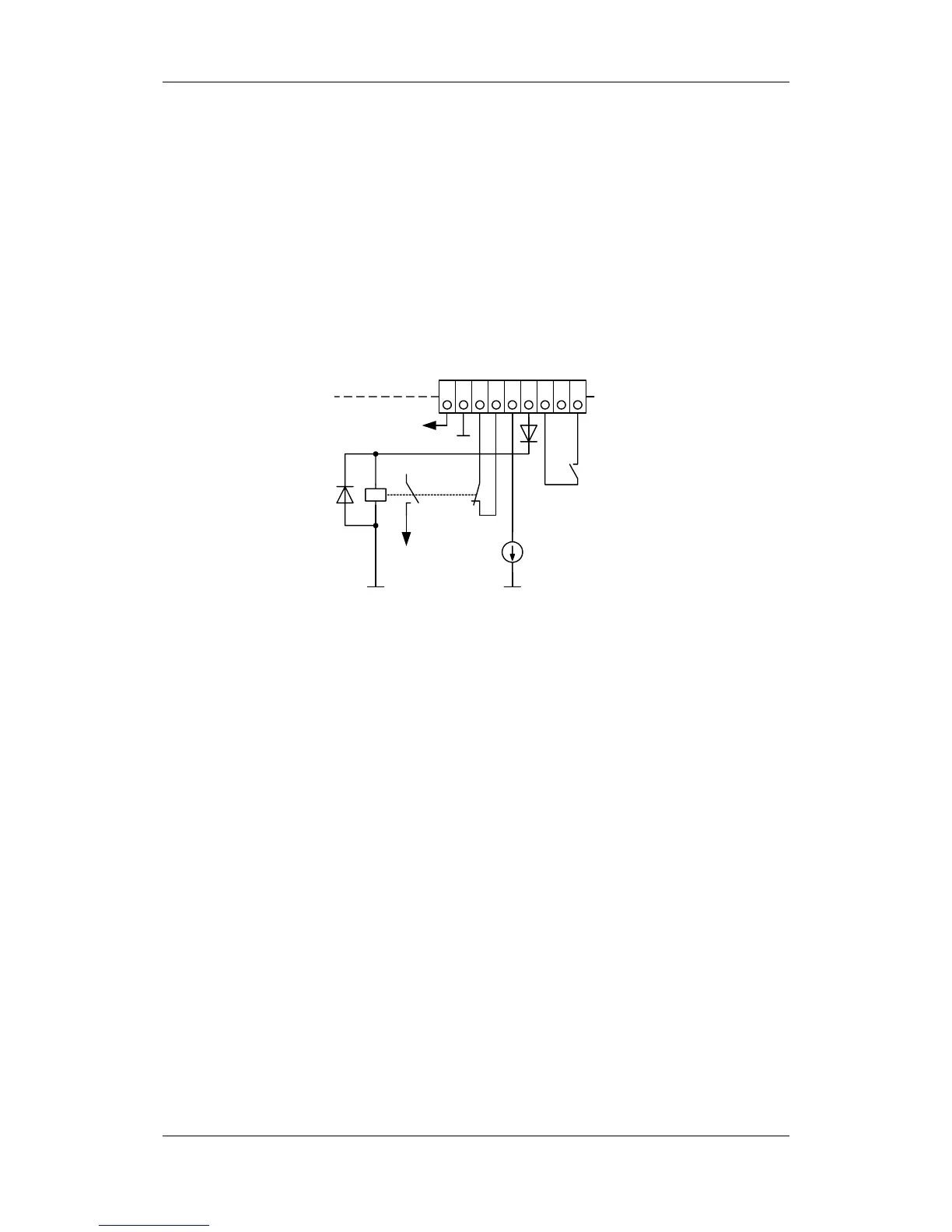
The field coil of the safety relay is connected at one end to the
grounded electronics frame. When the field coil is supplied via an
external 24 V supply, its negative pole must be connected to ground
potential. The external 24 V supply must comply with the requirements
for PELV circuits to EN 50178 (DIN VDE 0160).
In the shipped state, a jumper is inserted between terminals 5 and 6.
The jumper must be removed before the "SAFE STOP" function can be
used and an external control for selecting the function connected.
If the safety relay is supplied via the internal supply at X9:5, the
external 24 V supply must deliver at least 22 V at terminal X9:1/2 to
ensure that the relay picks up reliably (internal voltage drop).
1 42 3
Optocoupler /
fibre optics
supply
P15
Terminal strip
- X9
5 6 7 8 9
P24
electronic