Forming 05.2006
6SE7087-2JD60 Siemens AG
12-2 Operating Instructions SIMOVERT MASTERDRIVES
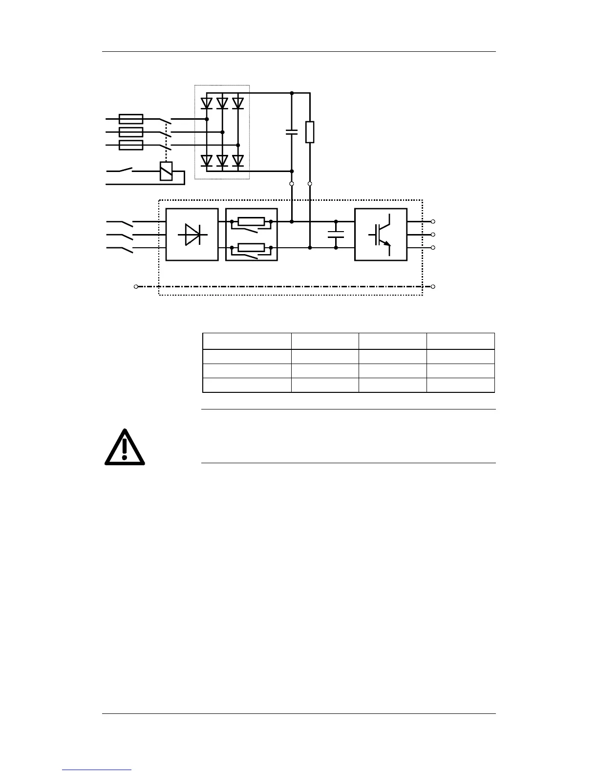
Motor-
connection
U2/T1
V2/T2
W2/T3
PE2
DC link
U1/L1
V1/L2
W1/L3
InverterPre-chargingRectifier
C / L+ D / L-
PE1
Disconnect
AC R
Forming
3AC
Fig. 12-1 Forming circuit
Vrated A R C
3AC 200 V to 230 V SKD 50 / 12 220 Ω / 100 W 22 nF / 1600 V
3AC 380 V to 480 V SKD 62 / 16 470 Ω / 100 W 22 nF / 1600 V
3AC 500 V to 600 V SKD 62 / 18 680 Ω / 100 W 22 nF / 1600 V
The unit has hazardous voltage levels up to 5 minutes after it has been
powered down due to the DC link capacitors. The unit or the DC link
terminals must not be worked on until at least after this delay time.
♦ Before you form the unit, all mains connections must be
disconnected.
♦ The converter incoming power supply must be switched off.
♦ The unit is not permitted to receive a switch-on command (e.g. via
the keyboard of the PMU or the terminal strip).
♦ Connect the required components in accordance with the circuit
example.
♦ Energize the forming circuit. The duration of forming is approx. 1
hour.
Components for the
forming circuit
(suggestion)
DANGER
Procedure