Allacciamento 05.2006
6SE7087-2JD60 Siemens AG
7-16 Istruzioni di servizio SIMOVERT MASTERDRIVES
Sulla morsettiera di comando si trovano i seguenti allacciamenti:
♦ 4 ingressi ed uscite parametrizzabili a scelta
♦ 3 ingressi digitali
♦ 24 V alimentazione ausiliaria (max. 150 mA) per ingressi ed uscite
♦ 1 interfaccia seriale SST2 (USS / RS485)
Se gli ingressi digitali vengono alimentati con una fonte esterna 24 V,
questa deve essere riferita alla massa X101.2. In questo caso il
morsetto X101.1 (P24 AUX) non può essere collegato con
l'alimentazione 24 V.
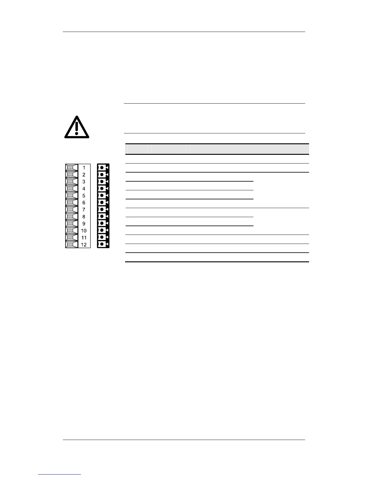
Mors. Indicazione Significato Campo
1 P24 AUX alimentazione ausiliaria DC 24 V / 150 mA
2 M24 AUX potenziale referenza 0 V
3 DIO1 ingresso/uscita digitale 1
4 DIO2 ingresso/uscita digitale 2
5 DIO3 ingresso/uscita digitale 3
6 DIO4 ingresso digitale 4
24 V, 10 mA / 20 mA;
L
≤ 3 V, H ≥ 13 V
7 DI5 ingresso digitale 5
8 DI6 ingresso digitale 6
9 DI7 ingresso digitale 7
24 V, 10 mA;
L
≤ 3 V, H ≥ 13 V
10 RS485 P allacciam. bus USS - SST2 RS485
11 RS485 N allacciam. bus USS - SST2 RS485
12 M RS485 potenziale refer. RS485
Sezione allacciabile: 0,14 mm
2
a 1,5 mm
2
(AWG 16)
Morsetto 1 si trova montato sopra.
Tabella 7-6 Morsettiera di comando X101
X101 – morsettiera
comando
ALLARME