Do you have a question about the SIGLENT TECHNOLOGIES SDG1032X and is the answer not in the manual?
Information regarding all rights reserved by SIGLENT TECHNOLOGIES CO., LTD.
States SIGLENT is a registered trademark of SIGLENT TECHNOLOGIES CO., LTD.
Lists product protection, modification rights, publication replacement, copying restrictions, and liability limitations.
Mentions conformance to national, industrial, and ISO standards.
Emphasizes that only qualified technicians should perform service procedures on the instrument.
Instruction to use only the special power line approved by local state.
Importance of connecting the ground conductor to the earth for safety.
Caution against connecting signal wire to high voltage or touching exposed contacts.
Advises to check all ratings and instructions before connecting the instrument.
Recommends professional check if instrument damage is suspected.
Warning not to touch exposed contacts or components when power is on.
Prohibition of operating the instrument in wet or damp environments.
Prohibition of operating the instrument in an explosive atmosphere.
Instruction to maintain the instrument's surface clean and dry.
Explains terms like DANGER, WARNING, and CAUTION used on the instrument.
Lists and explains symbols like Hazardous Voltage, Protective Earth Ground, Warning, etc.
Introduces the main technology characteristics of the SDG1000 generator.
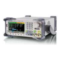
Briefly introduces the buttons and knob on the front panel.
Introduces all ports for easy communication on the rear panel.
States that Chapter 1 lists the generator's specifications.
Explains that Chapter 2 prepares the generator and familiarizes users with front-panel features.
States that Chapter 3 provides performance verification tests.
Explains that Chapter 4 provides disassembly procedures for structure understanding.
Explains that Chapter 5 provides troubleshooting procedures for internal boards and general issues.
States that Chapter 6 provides information on maintenance and daily care.
Lists the types of SDG1000 series generators with their analog bandwidth and channels.
Details the analog bandwidth for each SDG1000 series generator type.
Specifies the number of channels for each SDG1000 series generator type.
Lists key features like DDS technology, TFT display, sampling rate, resolution, waveforms, modulation, I/O, USB support, and languages.
Lists numbered components on the front panel with their descriptions.
Provides descriptions for numbered components of the front panel.
Identifies the ON/OFF switch on the front panel.
Identifies the USB Host port on the front panel.
Identifies the SIGLENT logo on the front panel.
Identifies the model number display on the front panel.
Identifies the switch for controlling the menu on the front panel.
Identifies the digital keypad on the front panel.
Identifies the universal knob for adjustments on the front panel.
Identifies the direction keys for navigation on the front panel.
Identifies the keys for controlling output functions on the front panel.
Identifies the BNC connectors on the front panel.
Identifies the general function keys on the front panel.
Identifies the keys for selecting waveforms on the front panel.
Identifies the keys for operating menus on the front panel.
Identifies the LCD display on the front panel.
Describes the output status indicators on the display.
Identifies parameter names shown on the display.
Identifies the units for displayed parameters.
Indicates the value part of displayed parameters.
Refers to the area on the display showing channel information.
Identifies the softkeys displayed on the screen.
Shows modulation-related information on the display.
Shows trigger-related information on the display.
Identifies the terminal for external 10 MHz reference input.
Identifies the terminal for sync output.
Identifies the chassis ground connection point.
Identifies the AC power socket.
Identifies the USB device port.
Identifies the terminal for external trigger, gate, FSK, and burst signals.
Identifies the terminal for external modulation input.
Safety warning regarding proper grounding for electric shock protection.
Lists detailed technical specifications for SDG1000 series generators, including model, frequency, resolution, etc.
Lists available waveforms: Sine, Square, Ramp, Pulse, Noise, Arb.
Specifies the frequency range for Sine waveforms across different models.
Specifies the frequency range for Square waveforms across different models.
Specifies the frequency range for Pulse waveforms across different models.
Specifies the frequency range for Ramp waveforms across different models.
Specifies bandwidth for Gaussian white noise across models.
States the resolution for arbitrary waveforms.
Details accuracy specifications over time and temperature.
Specifies the temperature coefficient for accuracy.
Lists harmonic distortion, spurious signal, and phase noise for sine waves.
Details specifications for square waves like rise/fall time, overshoot, duty cycle, jitter.
Specifies the range and resolution for pulse width.
Specifies typical rise/fall time for pulses.
Specifies the range and resolution for duty cycle.
Specifies the typical overshoot for pulses.
Specifies the typical jitter for pulses.
Specifies linearity for ramp waveforms.
Specifies symmetry range for ramp waveforms.
Specifies the length of arbitrary waveforms.
Specifies vertical resolution for arbitrary waveforms.
Specifies the sample rate for arbitrary waveforms.
Specifies minimum rise/fall time for arbitrary waveforms.
Specifies RMS jitter for arbitrary waveforms.
Details storage capacity for arbitrary waveforms.
Details output specifications for CH1 and CH2, including amplitude and impedance.
Lists amplitude ranges for CH1 and CH2 under different load conditions.
Specifies vertical resolution for sine waveform at 100 kHz.
Specifies amplitude flatness relative to a 100 kHz sine wave.
Specifies phase deviation between channels.
Specifies crosstalk between channels.
Specifies DC voltage ranges for CH1 and CH2.
Specifies the accuracy of the DC offset.
Specifies the output impedance.
Details the output protection mechanism.
Lists available carrier types for AM modulation.
Specifies modulation source options.
Lists available modulation waveforms.
Specifies the range for modulation depth.
Lists available carrier types for FM modulation.
Specifies modulation source options.
Lists available modulation waveforms.
Specifies frequency deviation for FM modulation.
Lists available carrier types for PM modulation.
Specifies modulation source options.
Lists available modulation waveforms.
Specifies deviation range for PM modulation.
Lists available carrier types for FSK modulation.
Specifies modulation source options.
Specifies modulation waveform for FSK.
Lists available carrier types for ASK modulation.
Specifies modulation source options.
Specifies modulation waveform for ASK.
Specifies frequency range for PWM modulation.
Specifies modulation source options.
Lists available modulation waveforms for PWM.
Specifies the range for external modulation.
Lists available carrier types for sweep functions.
Specifies sweep type (linear/logarithmic).
Specifies sweep direction (up/down).
Specifies the sweep time range.
Lists trigger source options for sweep.
Lists available waveforms for burst mode.
Specifies burst type (count, infinite, gated).
Specifies phase for burst start/stop.
Specifies the internal cycle range for burst.
Specifies gated trigger options for burst.
Lists trigger source options for burst.
Details external modulation specifications.
Details external trigger specifications.
Warning about exceeding external input voltage limits.
Specifies voltage level for trigger input.
Specifies trigger slope options.
Specifies pulse width for trigger input.
Specifies input impedance for trigger input.
Specifies voltage level for trigger output.
Specifies pulse width for trigger output.
Specifies output impedance for trigger output.
Specifies maximum frequency for trigger output.
Specifies voltage level for SYNC output.
Specifies pulse width for SYNC output.
Specifies output impedance for SYNC output.
Specifies maximum frequency for SYNC output.
Lists measurables: Frequency, Period, Pulse width, duty cycle.
Specifies frequency range for the counter.
Specifies frequency resolution.
Details voltage range and sensitivity for measurements.
Specifies the DC offset range.
Lists DC coupling ranges and sensitivities.
Specifies manual settings for DC coupling.
Lists AC coupling ranges and sensitivities.
Specifies parameters for pulse width and duty cycle measurement.
Details input adjustment settings.
Specifies input impedance.
Lists coupling methods (AC, DC).
Specifies high-frequency rejection setting.
Specifies the trigger level range.
Details display type, resolution, color depth, contrast, and backlight intensity.
Specifies voltage, consumption, and fuse rating.
Details operating and storage temperature, cooling method, and temperature range.
Specifies operating and storage altitude limits.
Lists dimension and weight of the instrument.
Specifies the physical dimensions of the generator.
Specifies the net and gross weight of the generator.
Indicates the IP protection rating.
Specifies the calibration cycle period.
Guides on preparing the generator for initial operation.
Instructions on adjusting the carrying handle.
Steps to set the output frequency.
Steps to set the output amplitude.
Steps to set the DC offset voltage.
Steps to adjust the duty cycle of a square wave.
Steps to adjust the symmetry of a ramp wave.
Steps to configure a pulse waveform.
Steps to configure a noise waveform.
Steps to select the DC Volts function.
Steps to output a built-in arbitrary waveform.
Instructions on using the built-in help system.
Lists supplied accessories and advises to contact sales office if items are missing or damaged.
Guides on connecting power and turning on the generator, including self-test.
Information on error messages during power-on self-test and service return.
Describes how to adjust the carrying handle's position.
Illustrates pulling the handle down.
Illustrates pulling the handle forward for carrying.
Instructs to press the Freq/Period softkey to access frequency settings.
Guides on inputting the frequency value using the keypad and selecting the unit.
Mentions using the knob and direction keys for input.
Instructs to press the Ampl/HLevel softkey to access amplitude settings.
Guides on inputting the amplitude value and selecting the unit.
Mentions using the knob and direction keys for input.
Instructs to press the Offset/LLevel softkey to access offset settings.
Guides on inputting the DC offset value and selecting the unit.
Mentions using the knob and direction keys for input.
Guides on selecting the square wave function and setting frequency.
Instructs to press the Duty softkey to access duty cycle settings.
Guides on inputting the duty cycle value and selecting the unit.
Guides on selecting the ramp wave function and setting frequency.
Instructs to press the Symmetry softkey to access symmetry settings.
Guides on inputting the symmetry value and selecting the unit.
Guides on selecting the pulse function.
Guides on setting the pulse period.
Guides on setting the pulse width.
Guides on setting the pulse delay.
Guides on selecting the noise function.
Guides on setting the variance for noise waveform.
Guides on setting the mean for noise waveform.
Guides on accessing the Utility function.
Guides on setting the DC voltage as an offset value.
Guides on selecting the arbitrary waveform function and loading a waveform.
Guides on selecting a specific built-in arbitrary waveform.
Guides on outputting the selected arbitrary waveform.
Guides on accessing and navigating the help system.
Instructions on how to exit the help system.
Lists recommended instruments for performance verification.
Provides recommendations for optimal performance during testing.
Explains the purpose and frequency of performance verification tests.
Outlines actions if the instrument fails verification.
Instructions for connecting a DMM for DC voltage measurement.
Steps to enable DC system and channel 1.
Guides on setting output values and measuring with DMM.
Instructs to compare measured voltage with specified ranges.
Steps to set up the generator for duty cycle verification.
Instructions for connecting the oscilloscope.
Guides on using oscilloscope features for duty cycle measurement.
Steps to measure duty cycle at 80%.
Instructions to repeat verification for channel 2.
Instructs to compare measured duty cycle with specified ranges.
Steps to configure the generator for frequency response test.
Instructions for connecting test equipment.
Guides on setting waveform parameters for the test.
Instructions to repeat verification for channel 2.
Instructs to compare measured power meter values with specifications.
Steps to configure the generator for AC amplitude verification.
Instructions for connecting test equipment.
Guides on setting amplitude values for the test.
Instructions to repeat verification for channel 2.
Instructs to compare measured power meter values with specifications.
Information on security measures needed before and during disassembly.
Lists the removable modules of the generator.
Lists the necessary tools for disassembly procedures.
Explains how to remove and install modules in detail.
Lists modules by their number.
Lists the names of removable modules.
Identifies the handle as a removable module.
Identifies the main metal shell and rear cabinet.
Identifies the front shell as a removable module.
Identifies the display module.
Identifies the rear metal cover.
Specifies the required tool for disassembly.
Provides an overview of the instrument's disassembly and safety precautions.
Details the steps to remove the handle.
Specific instruction for removing the handle.
Instruction for installing the handle.
Illustrates the removal of rear cabinet screws.
Illustrates the removal of metal shell screws.
Outlines the steps to remove the metal shell and rear cabinet.
Specific step for removing rear cabinet screws.
Specific step for removing the bottom screw.
Step to separate the cabinet and shell from the main body.
Instruction for installing the metal shell and rear cabinet.
Outlines the steps to remove the front cabinet.
Step to disconnect the front module cable.
Step to remove front cabinet screws.
Step to detach the front cabinet.
Instruction for installing the front cabinet.
Outlines the steps to remove the display module.
Step to remove screws from the keypad circuit board.
Step to remove circuit board, keypad, and screen.
Step to remove the universal knob.
Instruction for installing the display module.
Outlines the steps to remove the main body.
Step to remove rear metal cover screws.
Step to detach the rear metal cover.
Step to remove screws from main and power supply boards.
Step to separate boards from the main body.
Instruction for installing the main body.
Precautions to avoid damage to components due to electrostatic discharge.
Lists the equipment necessary for troubleshooting.
Instructs user to refer to a drawing for test points on the main board.
Safety precautions and introduction to power supply testing.
Step to check the fuse.
Steps to access and disconnect the power connector.
Guides on testing power supply voltages at the connector pins.
Important note about the power supply fuse and replacement.
Introduction and precautions for checking the main board.
Step to check connector connections on the main board.
Guides on checking voltage values at test points on the main board.
Explains testing of TA15 for CH1 output waveform issues.
Explains testing of TA16 for CH2 output waveform issues.
Explains testing of T4 for mainboard clock signal.
Troubleshooting steps for failure to start up.
Troubleshooting steps for a dark screen upon startup.
Troubleshooting steps for unresponsive buttons or abnormal screen display.
Troubleshooting steps for incorrect output frequency measurements.
Summarizes SIGLENT's warranty terms and service arrangements.
Instructions for preparing the unit for shipment for service or repair.
Step to tag the unit for service.
Step to place the unit in its original container.
Step to secure the shipping container.
Contact information for SIGLENT's headquarters in China.
Contact information for SIGLENT Technologies America, Inc.
Contact information for SIGLENT TECHNOLOGIES EUROPE GmbH.
| Brand | SIGLENT TECHNOLOGIES |
|---|---|
| Model | SDG1032X |
| Category | Portable Generator |
| Language | English |