57
EN
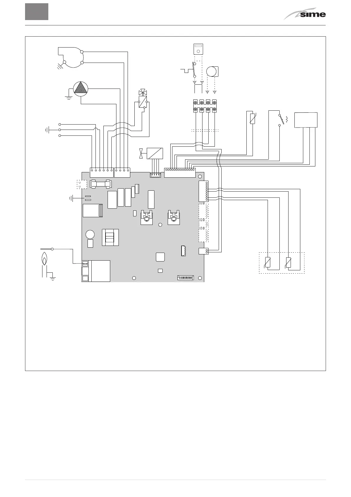
5.11 Wiring diagram
BROWN
BLUE
BLUE
BLUE
RED
RED
RED
RED
RED
GREEN
WHITE
RED
RED
BLUE
CD .6324910
BROWN
BLACK
BLUE
BLACK
230 V - 50 Hz
L
N
BLACK
BROWN
VD
SS
TRA
EAR
EV
F
PI
V
PA
FLM
CN6
CN5
CN3
CN17
CN4 CN1
CN15
CN14
CN13CN12
CN11
2
3
VCC
GND
IN
CN2
BLACK
BLACK
BLUE
BLUE
3456
SE
TA
CR
L
Line
N
Neutral
F
Fuse (3.15AT)
TRA
Ignition transformer
PI
System pump
V
Fan
EAR
Ignition / Detection electrode
EV
Gas solenoid valve
SS
Domestic hot water sensor
SM1-2
Dual sensor (thermal safety/delivery)
FLM
Flow meter
VD
Diverter valve
PA
Water pressure switch
TA
Air thermostat
SE
External sensor
CR
Remote control (instead of air
thermostat)
To connect the "Air Thermostat" or, alternatively the "Remote Control", remove the bridge
between terminals 5-6.
Fig. 15
m
CAUTION
Users must:
– Use an omnipolar cut-off switch, disconnect switch
in compliance with EN Standards
– Respect the connections L (Live) - N (Neutral)
– Ensure that the special power cable is only replaced
with a cable ordered as a spare part and connected
by professionally qualified personnel
– Connect the earth wire to an effective earthing
system. The manufacturer is not responsible for any
damage caused by failure to earth the appliance or
failure to observe the information provided in the
wiring diagrams.
d
IT IS FORBIDDEN
To use water pipes for earthing the appliance.