80
EN
8.3.2 Cleaning the burner
The burner does not require any particular maintenance simply
dust it with a soft brush.
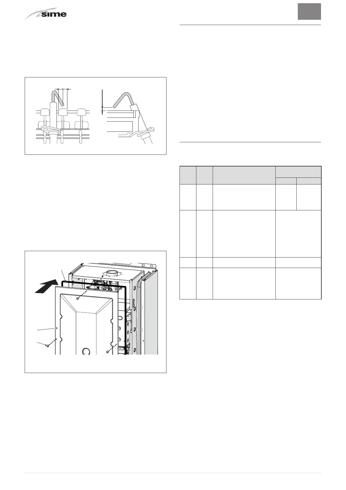
8.3.3 Checking the ignition/detection electrode
Check the state of the ignition/detection electrode and replace
if necessary. Check the measurements as per the drawing
whether the ignition/detection electrode is replaced or not.
3,5
+0,5
-0,5
Fig. 59
m
CAUTION
The position of the electrode is essential for the correct
detection of current ionization.
8.3.4 Final operations
After having cleaned the heat exchanger and the burner:
– remove any carbon residue using a vacuum cleaner
– check that the gasket and the insulation of the front panel (6)
of the combustion chamber and the gasket (13) of the front
panel (4) of the sealed chamber are all integral. If they are
not, replace them
– refit the panels (6) and (4) securing them with fastening
screws.
Fig. 60
8.4 Checks
8.4.1 Checking the smoke duct
It is recommended that the user checks that the combustion air
inlet duct and smoke outlet duct are integral and airtight.
8.4.2 Checking the expansion vessel pressure
It is recommended that the expansion vessel on the water side
is drained and that the prefilling pressure is not less than
1 bar
.
If this is not the case, pressurize it to the correct value (see
sectionExpansion vessel".
Once the checks described above have been completed:
– refill the boiler as described in section "REFILL operations"
– start the boiler up and carry out a smoke analysis and/or
measure the combustion efficiency.
– refit the front panel securing it with the two screws which
were removed previously
8.5 Unscheduled maintenance
If replacing the
electronic board
, the user MUST set the
parameters as indicated in the table.
Type No. Description
Setting for
Brava
One BF
25 30
tS 0.1
Index showing boiler power
in kW
0 = 25; 1 = 30 or the type of
exchanger = 4 (aluminium for
25 kW)
0 or 4 1
tS 0.2
Hydraulic configuration
0 = rapid
1 = storage tank with
thermostat or heating only
2 = hot water tank with
sensor
3 = bithermic
4=instant with solar power
input
0
tS 0.3
Gas Type Configuration
0 = G20; 1 = G31
0 or 1
tS 0.4
Combustion configuration
0 = sealed chamber with
combustion control
1 = open chamber with smoke
thermostat
2 = low NOx
0
To enter "Parameter setting and display"refer to the indications
provided in the specific section.
Once the parameters in the table have been set, you must carry
out the "Automatic calibration procedure".
If the
gas valve
and/or the
ignition/detection electrode
and/or the
fan
are replaced, the user must still carry out the entire phase
of "Automatic calibration procedure" described in the specific
section.